background image

2524 

Master Clock Installation

General Information

Description

The Rauland 2524 combines the full features of a master

clock with intercom-control ability. As a master clock, it can

correct virtually any secondary clocks and control up to 350

“events” (such as ringing bells or turning lights and equipment

on and off).

2524 

Clock and 

Communications 

Installation 


 KI-1628

2524 

Clock and 

  P r o g r a m m i n g  


  K I - 1 6 2 9

2524 

C l o c k   a n d   C o m m u n i c a t i o n s  


  K I - 1 6 3 0

These manuals cover both communications and clock functions.

The unit’s 

 and keypad make it easy to enter and check

all programming. Of special note is the ease with which any part

of the programming can be accessed and changed without

having to cycle through many other parts and without having

to re-enter everything else.

Unpacking

Manuals

This manual tells how to install the 2524 for clock functions

only. Instructions on programming and operating the 2524 for
clock functions only are in KI-1733.

The 

2524 is 

shipped with all the hardware needed to mount

it in a rack. Locate the following items before discarding the

packing material:

Rauland

Description

Part No.

4

 x 

 black machine screw.

B0439

4

 Flat Washer.

4

Fiber Washer.

4

Tinnerman for 

 mounting screw.

AB3640

Communications Functions

For information on communications functions, refer to the

following manuals:

Specifications

Programming Capacity:

Up to 350 Events and 100 Holidays.

LED Digit Displays:

Mode, Time, and Schedule.

LED Indicators:

AM 

and 

P M

8 Zones/Outputs

7 Days,

Music, Clock, and Communication 

(

COMM

).

Keyboard:

18 Buttons: 

 through 9,” Left and Right Cursors,

four functions, 

Clock-Comm 

select, 

and 

Manual.

outputs:

8 Zone/Output contacts, each with a relay 


Amp resistive).

Power Failure Back-up:

Five-year, 3-volt lithium battery.

Power Required:

120-230 volts, 50 or 60 Hz, 20 watts.

Dimensions:

19” (48.3 cm) panel, 3” (8.9 cm) high, 9” (24.1 

cm)

deep (including rear conduit box).

Net Weight:

 (4.1 kg).

Planning

The attached wiring diagrams show typical installations for

the 2524 used as a master clock. There is also helpful information

further 

on, in “Associated Equipment.”

Zones

What may require closer attention in more complex 


 l 

t.- 


  I ”  


thorough explanation of “zones,” consult the 2524 

 manual, KI-1733. Briefly, remember that outputs

used for clock corrections or equipment control cannot be 

used

for other “events,” such as clock tones and music on class

changes. You will also need to coordinate the wiring of secondary

clocks 

with the “Mode A” and clock-code programming mode.

Be sure to till out the “Zones Chart” (in the programming


Page 

2

Summary of Contents for 2524 ChronoCom

Page 1: ...Cover Signaling Devices and Equipment Correctable Secondary Clocks With Separate Telecenter Systems Turning on the 2524 Functional Descriptions 6 Music Events 6 With Separate Telecenter Systems 6 As...

Page 2: ...For information on communications functions refer to the following manuals Specifications Programming Capacity Up to 350 Events and 100 Holidays LED Digit Displays Mode Time and Schedule LED Indicator...

Page 3: ...rs to split the load increases the total load that the output can handle GND A chassis ground which also serves as the circuit common It should be used when connecting a 2417 Correction Adapter Module...

Page 4: ...a few helpful details Screw Terminal Cover To access the screw terminals remove the shield from the bottom of the electrical box that is attached to the rear of the chassis on the right as viewed fro...

Page 5: ...mon Notes 1 The MIO is the Main Input Output Board in the Tele center IV 2 The MIO has wire wrap terminals and the 2524 has screw terminals 3 Use 22 AWG tinned cable for all connections 4 Do not conne...

Page 6: ...and its outputs are connected to a Telecenter system to provide time tone signals Since the 2524 s ribbon cable does not connect to the speaker relay boards it cannot send music to individual rooms o...

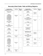
Page 7: ...30 NNE SR 030 NNE SRLV 060 12E SR and 060 12E SRLV NN any two digit number Synchronous Wired Dukane 24BF209 24BF212 707 8 and 707 9 types Synchronous Wired old type Reference Figure 1 or2 3 4 Secondar...

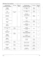
Page 8: ...anklin Bi Polar Mark 5M Impulse Wiring more than 25 Special digitals for 24 VAC Application Wiring more than 25 Special digitals for 120 VAC Application Rauland Special Wiring for 24 VAC Application S...

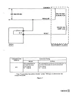
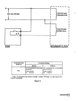
Page 9: ...120 24VAC CORR COIL I I I I I I I I I I I I I I 1 3 I I I I I I L J SECONDARY CLOCK Correction Code Mode A Correction Timing From X 00 00 To X 00 25 From 6 00 00 See Correctable Secondary Clocks unde...

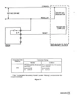
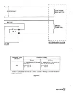
Page 10: ...C I RUN MOTOR I I I I RESET I 120 24 VAC CORR COIL Correction Code I I I I I I I I I I I I I I I I d SECONDARY CLOCK From X 00 00 To X 00 25 See Correctable Secondary Clocks under Wiring to determine...

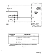
Page 11: ...ly I 12 Hour I Y is activated for 38 seconds every hour X is activated for 14 seconds From X 57 39 every 12 hours To X 58 17 From 5 57 54 X is activated for 8 seconds every hour I To 5 58 08 From X 57...

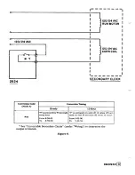
Page 12: ...Correction Code Mode A I I f 120 24VAC CORR COIL I I Pam BRAY ea d SECONDARY CLOCK I I T I I I I I I I I I I I I I From X 56 05 From 11 56 00 To X 56 15 See Correctable Secondary Clocks under Wiring P...

Page 13: ...I I 120 24 VAC I RUN MOTOR I 120 24VAC CORR COIL I I I I I I I I I I I I I I I Correction Code From X 00 00 Not Applicable See Correctable Secondary Clocks under Wiring to determine the output termin...

Page 14: ...ction Code Correction Timing Hourly Y is activated for 57 seconds every hour From X 57 03 To X 58 00 12 Hour Y is activated in 11 cycles 57 sec onds on 63 seconds off From 5 59 03 TO 6 20 00 See Corre...

Page 15: ...I I Correction Code Mode A 07 Correction Timing Hourly X is activated for 59 minutes 6 seconds every hour From x 44 59 To x 1 44 05 Y is activated for 54 seconds every hour From X 44 05 To X 44 59 12...

Page 16: ...n Timing 12 Hour 08 Y is activated for 55 seconds Y is activated on and off 12 times 65 sec every hour onds on and 25 seconds off every 12 hours From X 58 05 From 5 05 00 To X 59 00 To 5 22 35 See Cor...

Page 17: ...de A 09 I I I I I I I I I I I I I I I aw I SECONDARY CLOCK Correction Timing every hour From X 00 00 From 5 12 00 To X 59 25 Y is activated for 35 seconds every hour From X 59 25 To X 00 00 See Correc...

Page 18: ...te Impulse I Y is activated for 2 seconds every minute From X XX 58 To X XX 00 X is pulsing at the rate of 1 second on and 1 second off Not Applicable See Correctable Secondary Clocks under Wiring to...

Page 19: ...I I I I I I I I I I I I I I SECONDARY CLOCK is activated for 59 minutes 6 seconds To X 1 58 05 Y is activated for 54 seconds every hour Not Applicable See Correctable Secondary Clocks under Wiring to...

Page 20: ...I I I I I I 1 I I I I I I Hourly is activated for 8 seconds every hour From X 57 54 To X 58 02 l2 Hour X is activated for 14 seconds every 12 hours From 5 57 54 To 5 58 08 See Correctable Secondary Cl...

Page 21: ...48VDC I I I I I I I I D1 I B w 2524 SECONDARY CLOCK D1 AND D2 ARE 1N3210 OR EQUIVALENT i IMPULSE COIL From X XX 58 See Correctable Secondary Clocks under Wiring to determine the output terminals Figur...

Page 22: ...i SECONDARY CLOCK ICorrection Code Mode A Correction Timing Minute Impulse Hourly minute From X XX 58 To X XX 00 From X 59 02 X is activated for 50 minutes every hour See Correctable Secondary Clocks...

Page 23: ...dd Arc Suppression 1 Circuit as shown I R 10 c 1F 600 VDC I I SECONDARY CLOCK From X XX 58 To X 59 48 X activates the external relay reversing of the pulses for 50 minutes RY1 is a customer provided24...

Page 24: ...210 OR EQUIVALENT X is activated for 2 seconds X is activated 16 cycles 1 second on 2 sec From X XX 58 From X 59 02 provides 24 VDC pulses Y is activated for 3 times each hour for 2 seconds on 58 seco...

Page 25: ...itive pulse to the im pulse coil for 2 seconds every minute From X XX 58 To X XX 00 Hourly Y is activated for 15 cycles 1 second on 2 seconds off From X 58 10 To X 58 55 X activates the external relay...

Page 26: ...AND D2 ARE lN3210 OR EQUIVALENT Minute Impulse X is activated for 2 seconds every minute Hourly Y is activated 10 seconds every hour From X 59 40 To x 59 50 From X XX 58 To X XX 00 Except for the 59t...

Page 27: ...CLOCK Hourly Correction Timing Minute Impulse X is activated for 2 seconds every minute From X XX 58 To X XX 00 Except for the 59th minute Y is activated for 10 seconds every hour From X 59 40 To X 5...

Page 28: ...DED DPDT RELAY WITH 2524 24VDC COlL Code Mode A From X 51 58 To X 1 51 00 then for 19 cycles 2 seconds on 1 second off I I cc 1 x AN 1 4 l See Correctable Secondary Clocks under Wiring to determine th...

Page 29: ...Correction Timing Minute Impulse X is activated for 2 sec onds every minute From X XX 58 To X XX 00 Hourly is activated for 18 cycles 1 second on 2 seconds off From X 58 04 To X 58 56 Y is activated f...

Page 30: ...n Code Correction Timing l Correction every 24 hours at 12 0l a m l Correction when the time is set l Correction when power is restored after a power failure See Correctable Secondary Clocks under Wir...

Page 31: ...TERM B 2 IF11O VAC LINE CONNECT RELAY X TO 2416 TERM C 3 IF 130 VAC LINE CONNECT RELAY X TO 2416 TERM A l Correction every 24 hours at 12 0l a m l Correction when the time is set l Correction when pow...

Page 32: ...120VAC LINE 6 Note The DIG output is always available regardless of the zone configuration or the Correction Codes used Figure 24 r KM0976...

Page 33: ...ND DIGITAL BLK DIG 5VDC GND 2524 Z 2 2417 ICorrection Code Mode A Correction Timing None see Note l Correction every 24 hours at 12 0l a m l Correction when the time is set l Correction when power is...

Page 34: ...ds every even minute 2 seconds on 118 seconds off 30 cycles per hour From X 00 58 To X 58 58 Y is activated 2 seconds every odd minute 2 seconds on 118 seconds off 30 cycles per hour Not Applicable RY...

Page 35: ...BOTH 2415 S TO A OF 1ST 2415 TO A OF 2ND 2415 TO B OF 1ST 2415 TO B OF 2ND 2415 NOTE THE 2524 IS PROGRAMMEDFOR A CODE 20 CLOCK CORRECTION CONNECTING MORE THAN 25 DIGITAL CLOCKS TO A 2524 MASTER CLOCK...

Page 36: ...HE 2524 IS PROGRAMMEDFOR A CODE 20 CLOCK CORRECTION TO F OF BOTH 2416 s TO B OF 1ST 2416 TO B OF 2ND 2416 TO D OF 1ST 2416 TO D OF 2ND 2416 CONNECTING MORE THAN 25 DIGITAL CLOCKS TO A 2524 MASTER CLOC...

Page 37: ...LAY an autoformer NOTES 1 THE 2524 MASTER CLOCK IS PRE PROGRAMMEDTO OUTPUT RAULAND ANALOG CORRECTIONSIGNAL ON RELAY 7 IN THE SIX ZONE MODE OF OPERATION 2 MAXIMUMOF 25 CLOCKS ON THE 2415 POWER SUPPLY 3...

Page 38: ...2 Each box K represents a load signaling device or equipment Each load s current should be lim ited to 5 amperes resistive at 30 VDC or 125 VAC 3 O u t 7 and O u t 8 are normally used for clock corre...

Page 39: ...pin NOTES 1 The data transmission settings on the 2524 and device must match The 2524 s factory settings 1200 baud 1stop bit no parity and 8 data bits 2 The pin connections shown here apply only to a...

Page 40: ...2524 Clock and intercom Controller Jumpers 7 PROGRAMMING J3 r 1 ENABLE I DISABLE JUMPER I BAUD RATE I SELECTOR...

Reviews: