Rauch MDS 8.2 Operator'S Manual Download Page 34

Hopper cover

Application

AP 13

Basic hopper MDS 14.2

AP 19

Basic hopper MDS 18.2/20.2

Extensions: M 430, M 630

AP 240

Extensions: M 800, M 1100

4.4.3

Row spreading system

n

RFZ 7

All versions except MDS 8.2

This  7-row  spreading  system  is  suitable  for  depositing  dry,  granulated  fertilizer  in  rows  next  to
sprouting plants.

A separate operator’s manual is supplied with the row spreading system.
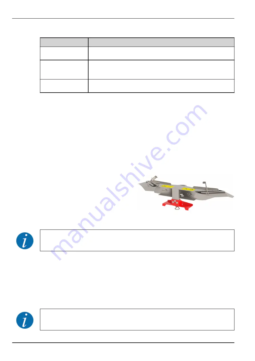
4.4.4

Row spreading system

n

RV 2M1 for hops and fruit cultivation

The  row  spreading  system  is  designed  such
that  an  approx.  1  m  wide  strip  is  spread,
depending  on  the  fertilizer,  for  each  row  to  the
right  and  left  of  the  machine  (row  spacing:
approx. 2-5 m).

Information about spreading with the special equipment can be found in chapter 

9.12 RV 2M1 row 

spreading system for hops and fruit cultivation

.

4.4.5

TELIMAT boundary spreading unit

n

TELIMAT T1

The  TELIMAT  limited  border  spreading  unit  is  used  for  remote-controlled  boundary  and  border
spreading from the track (left).

A double-acting valve is required for use of the TELIMAT T1 limited border spreading unit.

Information about spreading with the special equipment can be found in chapter. 

9.10.3 Adjusting 

the TELIMAT full and limited border spreading unit

4. Machine data

34

5902916

MDS 8.2/14.2/18.2/20.2

Summary of Contents for MDS 8.2

Page 1: ...ure use This operator s and assembly manual is an integral part of the machine Suppliers of new and second hand machines are required to document in writing that the operator s and assembly manual was...

Page 2: ...r machine Please note that damage caused by incorrect operation or improper use cannot be covered by warranty claims Please enter here the type and serial number together with the year of manufacture...

Page 3: ...ssioning the machine 13 3 5 4 Hazard zone 13 3 5 5 Running operation 14 3 6 Using fertilizer 14 3 7 Hydraulics system 15 3 8 Maintenance and service 15 3 8 1 Qualifications of maintenance personnel 16...

Page 4: ...ad calculation 38 6 Transport without tractor 41 6 1 General safety instructions 41 6 2 Loading and unloading parking 41 7 Commissioning 42 7 1 Accepting the machine 42 7 2 Tractor requirements 42 7 3...

Page 5: ...n the headland with TELIMAT T1 special equipment 99 9 12 RV 2M1 row spreading system for hops and fruit cultivation 102 9 12 1 Pre configuration of the machine 102 9 12 2 Adjustment of the row spacing...

Page 6: ...aulic hoses 138 11 13 Transmission oil 139 11 13 1 Quantities and types 139 11 13 2 Checking the oil filling level 139 11 14 Lubrication 140 11 14 1 Drive shaft lubrication 140 11 14 2 Lubricating oth...

Page 7: ...parts from RAUCH may be used as replacements The machine may only be used maintained and repaired by people who are familiar with the characteristics of the machine and who are aware of the risks The...

Page 8: ...owner The operator s manual is intended for the operator of the machine and anyone involved in operating and maintaining it It must be read understood and applied by every person who is entrusted wit...

Page 9: ...bullet points Property A Property B 2 3 3 References References to other sections in the document are shown with paragraph number header text and or page number Example Please also note 3 Safety Refer...

Page 10: ...to the severeness of the risk and the probability of its occurrence The warning symbols draw attention to the unavoidable residual risks inherent in the design to which users of the machine are expose...

Page 11: ...l regulations However its usage and maintenance may cause danger to the health and life of the operator or third parties and or the impairment of the machine and other material assets For this reason...

Page 12: ...specified in every country The owner of the machine is responsible for observing the regulations applicable in the country of operation The following instructions must also be observed Never let the...

Page 13: ...operating safety of the machine before the first and every subsequent commissioning Is all safety equipment at the machine installed and functioning Are all fasteners and load bearing connections tig...

Page 14: ...ng Only operate the machine with the protective grids in the hopper closed During operation the protective grid must neither be opened nor removed Rotating machine components can cause serious injury...

Page 15: ...ontamination of the hydraulic circuit Always suspend the couplings in the brackets provided Use the dust caps Clean the connections before coupling them Regularly check the hydraulic components and hy...

Page 16: ...the ignition key of the tractor Disconnect the power supply between the tractor and the machine before performing any maintenance and service tasks or before working on the electrical system Check th...

Page 17: ...Ihres Landes zur Benutzung ffentlicher Verkehrswege Achten Sie auf die vorschriftsm ige Anbringung 3 9 2 Road travel with the machine Handling steering and braking performance of the tractor are affe...

Page 18: ...ent warning and instruction notices reflector front 1 Protective grid lock 2 Instructions protective grid lock 3 Warning crushing hazard between the tractor and the machine 4 Warning Read operator s m...

Page 19: ...lector 3 Instructions tightening torque 4 Yellow side reflector 5 Warning Moving parts 6 Instructions Pulling a trailer 7 Warning Remove ignition key 8 Warning Ejection of material 9 Crane lugs 10 Ins...

Page 20: ...n of fertilizer to the front direction of tractor workplace The deflecting device and safety equipment prevents anything from being grabbed by rotating spreading discs from the front and reduces the r...

Page 21: ...spreading range of the machine Danger due to moving parts Danger of cutting off body parts It is prohibited to reach into the hazard zone of rotating parts Switch off the engine and remove the key bef...

Page 22: ...t can only be unlocked by using a tool Rated speed of the PTO shaft The rated speed of the PTO shaft is 540 rpm Maximum load capacity MDS 20 2 Maximum load capacity MDS 18 2 Maximum load capacity MDS...

Page 23: ...ensure that all necessary signs are present Depending on the country of destination additional signs can be attached to the machine Fig 4 Name plate 1 Manufacturer 2 Serial number 3 Machine 4 Type 5...

Page 24: ...d with a lighting system and front rear and side lighting for the attachment to the machine please refer to 3 10 1 Position of safety equipment as well as warning and instruction stickers 3 Safety 24...

Page 25: ...tion of the machine Use the machines in accordance with chapter 1 Intended use The machine consists of the following assemblies 1 chamber hopper Frame and coupling points Drive elements drive shaft an...

Page 26: ...Front 1 Hopper inspection window filling level scale 2 Scale for the application rate left right 3 Coupling points 4 Transmission spigot 5 Universal drive shaft mounting bracket 6 Hose and cable tray...

Page 27: ...sembly overview front side with weighing frame 1 Weighing frame 2 Hose and cable tray 3 Coupling points 4 Universal drive shaft mounting bracket 5 Weigh cells 4 Machine data MDS 8 2 14 2 18 2 20 2 590...

Page 28: ...w Rear 1 Frame 2 Spreading disc left right 3 Transmission The adjustment lever is located on the hopper on the left side direction of travel Fig 8 Adjustment lever position 4 Machine data 28 5902916 M...

Page 29: ...4 2 2 Agitator 1 Agitator 2 Metering slide Fig 9 Agitator 4 Machine data MDS 8 2 14 2 18 2 20 2 5902916 29...

Page 30: ...acting hydraulic cylinders Single acting hydraulic cylinder with two way unit Double acting hydraulic cylinders Spreading depending on forward speed Weigh cells VariSpread VS2 VS2 VS2 VS2 VS8 VS8 The...

Page 31: ...27 4 cm 27 4 cm 27 4 cm 27 4 cm Data MDS 8 2 MDS 8 2 W MDS 14 2 MDS 14 2 W MDS 18 2 MDS 18 2 W MDS 20 2 MDS 20 2 W Filling level Basic machine 92 cm 104 cm 93 cm 101 cm Filling width 98 cm 130 cm 180...

Page 32: ...2000 kg 4 3 3 Technical data for the extensions The machine can be operated with various attachments and attachment combinations The capacity dimensions and weights may change depending on the select...

Page 33: ...untries The available special equipment depends on the country of use of the machine and is not listed fully here Contact your dealer importer if you need specific special equipment 4 4 1 Extensions T...

Page 34: ...strip is spread depending on the fertilizer for each row to the right and left of the machine row spacing approx 2 5 m Information about spreading with the special equipment can be found in chapter 9...

Page 35: ...limiter 4 4 7 Hydraulic remote control unit for spreading width limiter This remote control is used from the tractor cabin to hydraulically swing the spreading width limiter into position or to swing...

Page 36: ...try of use of the attachment Contact your dealer importer if you need rear lighting Attachments are subject to the lighting regulations specified in the traffic regulations Observe the traffic regulat...

Page 37: ...5 For checking the cross distribution in the field Fig 10 PPS5 optional equipment 4 4 15 Fertilizer identification system n FIS Fast and uncomplicated determination of spreader settings when working w...

Page 38: ...s Description Obtained by T kg Tractor unladen weight Refer to the tractor operator s manual Measure on scale T1 kg Unladen load on tractor front axle Refer to the tractor operator s manual Measure on...

Page 39: ...ront rear combination 1 Calculation of the minimum front ballast weight M1 minimum M1 minimum M2 x c d T1 x b 0 2 x T x b a b Write the minimum additional weight in the chart Front tool 2 Calculation...

Page 40: ...y Indicate double 2 tires the authorized load value see tire manufacturer indications Table Actual value obtained by calculation Value authorized according to operator s manual Double value of the aut...

Page 41: ...n ensures that the machine is transported appropriately Unauthorized persons are to be kept away from the transport route Cordon off the affected areas Transport the machine cautiously and handle it w...

Page 42: ...en receiving the machine check that attached components are correctly and tightly positioned The right hand and left hand spreading discs must be mounted facing the direction of travel In case of doub...

Page 43: ...ersal drive shafts Standard drive shaft for standard machine frames See 7 3 1 Installing the standard drive shaft Tele Space drive shaft Special drive shaft for machine with weigh frame version W See...

Page 44: ...u Tighten the hex cap screw and nut using a size 17 wrench max 35 Nm Fig 13 Connecting the universal drive shaft u Push the universal drive shaft guard with hose clamp over the universal drive shaft...

Page 45: ...ring the universal drive shaft cover Notes for removal Dismount the universal drive shaft in reverse order of mounting Never use the suspension chain for suspending the universal drive shaft u Always...

Page 46: ...tractor symbol must point to the tractor u Remove the protective cap Fig 17 Loosening the universal drive shaft guard u Loosen the locking screw 1 of the drive shaft guard u Turn the universal drive s...

Page 47: ...sion spigot Fig 18 Pushing the universal drive shaft onto the transmission spigot u Place the universal drive shaft on the transmission spigot Fig 19 Fastening the universal drive shaft u Tighten the...

Page 48: ...o the extension housing of the transmission do not tighten u Turn the universal drive shaft guard to the locking position Fig 20 Attaching the universal drive shaft guard u Tighten the locking screw u...

Page 49: ...ne match if necessary consult your dealer Is the machine securely positioned on level and solid ground Do the axle loads conform to the stipulated calculations 7 4 2 Mounting DANGER Danger to life due...

Page 50: ...ch pins or spring clips Attach the machine according to the values in the fertilizer chart This guarantees correct cross distribution of the fertilizer Any oscillating movements during spreading are t...

Page 51: ...s u Switch off the tractor engine Remove the ignition key u Mount the universal drive shaft on the tractor w If there is not enough space available an extendable Tele Space universal drive shaft must...

Page 52: ...his may cause damage to the universal drive shaft to the gearbox or the machine u Check the clearance between the machine and the tractor u Make sure that there is enough space at least 20 to 30 mm be...

Page 53: ...body parts or objects Contact with the distribution unit may injure crush or cut off body parts u Maximum admissible mounting heights at front V and rear H are to be complied with at all times u Ensu...

Page 54: ...ng 850 850 Late fertilization 730 830 7 5 3 Set the mounting height based on the fertilizer chart The mounting heights in the fertilizer chart A and B are always measured in the field from the top of...

Page 55: ...Compare the mounting heights A and B plus the crop height with the maximum admissible mounting heights at the front V and rear H Fig 25 Mounting position and height during normal fertilizing u If the...

Page 56: ...ight from the fertilizer chart u Compare the mounting heights A and B plus the crop height with the maximum admissible mounting heights at the front V and rear H Fig 26 Mounting position and height du...

Page 57: ...lic slide actuator n Version K D D Mono Tractor requirements Version K two single acting control valves Version D two double acting control valves Version D Mono one double acting control valve Functi...

Page 58: ...vel or during filling close the two ball valves at the coupling plugs on the hydraulic lines This prevents automatic opening of the metering slide caused by leaks in the valves in the tractor hydrauli...

Page 59: ...uated individually by means of the two way unit s ball valves n Position display This display makes it possible to see the position of the metering slides from the driver s seat in order to prevent ac...

Page 60: ...parate operator s manual for the E CLICK operating unit This operator s manual is included in the scope of delivery 7 6 3 Connecting the electronic slide actuators The version Q machines are equipped...

Page 61: ...ed u Observe the admissible overall weight u Close the metering slide and if applicable the ball valves versions K u Only fill the machine when it is attached to the tractor Make sure that the tractor...

Page 62: ...Fig 30 Filling level scale graduated in liters 7 Commissioning 62 5902916 MDS 8 2 14 2 18 2 20 2...

Page 63: ...on must be conducted while the motor is running at a standstill or during travel over a test track You execute the calibration test for machine version Q on the control unit The calibration test is de...

Page 64: ...rmula Forward speed km h 360 Time over 100 m Example You need 45 seconds for 100 m 360 8 km h 45 s Determining the nominal output volume per minute To calculate the nominal output volume per minute yo...

Page 65: ...of the forward speed of 8 km h The nominal output volume per minute amounts to 72 kg min If calibration is only to be carried out at one outlet the total value of the nominal output volume is to be ha...

Page 66: ...nt unauthorized starting An adequately sized collection vessel is ready for collecting the fertilizer minimum capacity 25 kg Determine the empty weight of the collecting vessel Prepare the calibration...

Page 67: ...spreading discs must be removed u Remove the adjustment lever 1 from the bracket Fig 34 Adjustment lever position u Use the adjustment lever to loosen the cap nut of the spreading disc u Remove the sp...

Page 68: ...tion is selected Please observe the operator s manual for the control unit WARNING Risk of injury due to rotating machine parts Rotating machine components universal drive shaft hubs may catch and pul...

Page 69: ...ation rate stop is set correctly End calibration test Actual output volume target output volume Set the application rate stop to a higher position and repeat the calibration test Actual output volume...

Page 70: ...e tightening the nut Otherwise the cap nut is worn and must be replaced u Check that there is clearance between the spreading vanes and the outlet by turning the spreading discs by hand u Re mount the...

Page 71: ...the return spring is tensioned when the setscrew is loosened the stop lever may hit the end of the guide slot This may cause crushing injuries to fingers and or result in injury to the operating perso...

Page 72: ...during work carry out a calibration test Particularly hard fertilizer types such as Thomas fertilizer and kieserite increase the wear on the spreading vanes The spreading distance to the rear is appro...

Page 73: ...ne 111 9 3 Setting the application rate WARNING Risk of injury from rotating spreading discs The distribution unit spreading discs spreading vanes may catch and pull in body parts or objects Contact w...

Page 74: ...and to hold the stop lever in position during volume setting u Always observe the procedure for setting the application rate Setting the application rate u Close the metering slide Fig 39 Scale for se...

Page 75: ...ned incorrectly the operation of the actuators via the QUANTRON A operating unit may cause damage to the metering slides u Always clamp the stop levers at the maximum scale position For version Q the...

Page 76: ...u Do not remove deflectors mounted on the hopper n Structure of spreading disc M1 There are two identical spreading vanes on every spreading disc A spreading vane comprises a main vane and an extensio...

Page 77: ...are two spreading vanes on every spreading disc A spreading vane comprises a main vane with an extension vane The main vane of the right hand spreading disc has the designation BR and the correspondi...

Page 78: ...ng late fertilizing optionally right or left n Spreading vane angle settings Adjustment towards smaller numbers The angle of the spreading vane is moved back Adjustment towards larger numbers The angl...

Page 79: ...preading Example C3 B2 WARNING Risk of injury due to sharp edges The spreading vanes have sharp edges There is a danger to the hands when changing or setting the spreading vanes u Wear protective glov...

Page 80: ...NOTICE Danger of material damage Do not over bend the flat spring The flat spring tension must reliably lock the main and extension vanes onto the spreading disc If the flat spring is over bent then i...

Page 81: ...sing urea particular attention is to be paid to the following Because of fertilizer imports urea is available in widely varying qualities and particle sizes It may therefore be required to adjust the...

Page 82: ...C3 B2 n Example of full border spreading during normal fertilizing Fig 45 Full border spreading during normal fertilizing Full border spreading in normal fertilizing mode refers to a spreading techni...

Page 83: ...er spreading disc Normal fertilizing position C3 B2 n Example of field spreading during late fertilizing Fig 46 Field spreading during late fertilizing During field spreading in late fertilizing mode...

Page 84: ...eld boundary Specified parameters Type of fertilizer ENTEC 26 COMPO BASF Working width 12 m Spreading disc type M1 Forward speed 10 km h Application rate 300 kg ha On the full border spreading side bo...

Page 85: ...reading width assistant VariSpread you can reduce the spreading width and the application rate on each side Wedge shaped fields can thus be spread at high precision Some models are not available in al...

Page 86: ...ol unit to define the settings for the sections to achieve accurate spreading results in wedge shaped fields More detailed information about possible settings of the sections is provided in the operat...

Page 87: ...spread to the left or to the right actuate the corresponding control valve The hydraulic cylinder pulls the respective metering slide against the stop D Mono Spread to the left hand side The hydrauli...

Page 88: ...tilizer types please also see the supplementary manual for the practice test kit To check the spreading unit settings quickly we recommend using the layout for one pass To determine the spreading unit...

Page 89: ...u Make sure that the collecting vessels are placed on level ground Collecting vessels set at an angle can cause measuring errors see image above u Running the calibration test see 8 Calibration u Adj...

Page 90: ...ssels one in front of another at a distance of 1 m in the overlap zones between the tracks and one collecting vessel in the track according to Fig 51 n Run the spreading test with the determined open...

Page 91: ...u Select a similar fertilizer from the fertilizing charts and set the spreader accordingly u Set the mounting height of the machine as specified in the fertilizer chart Make sure that the mounting hei...

Page 92: ...placed one after another and pour them into the measuring tubes from the left hand side u The quality of the horizontal spreading pattern can be read off the three measuring tubes Fig 53 Possible res...

Page 93: ...second spreading vane indicated is not sufficient shorten the spreading vane length w e g C3 B1 to setting C3 A1 Case D Too little fertilizer in the overlap zones Reduce the amount of fertilizer in th...

Page 94: ...For limited border spreading you need the GSE 7 or TELIMAT T1 special equipment 9 10 1 Full border spreading from the first track u Set spreading vanes on the boundary side as specified in the fertil...

Page 95: ...u Slide the adjustment piece to the determined value u Tighten the locking nut 5 For the zero position place the two adjustment pieces on top of each other congruent Adjustment Limited spreading widt...

Page 96: ...4 m for limited border spreading only The TELIMAT T1 is mounted on the left side of the machine in the direction of travel You can control the TELIMAT unit from the tractor via a single acting control...

Page 97: ...e guiding plates are available inside the boundary spreading unit and can be moved along a numeric scale scale 1 to 7 The numeric scale is mainly used for setting the working width Coarse adjustment a...

Page 98: ...generally sufficient to modify the guiding plate setting To decrease the spreading distance relative to the calibration chart setting Change the position of the guiding plate on the numeric scale in...

Page 99: ...osition spreading errors may occur u Make sure that the unit is always in the specified end position u When switching from boundary spreading to normal spreading operate the control valve until the un...

Page 100: ...the field When continuing spreading in the field after headland track spreading note the following u Swivel the TELIMAT boundary spreading unit out of the spreading area upper position The TELIMAT bou...

Page 101: ...headland The tractor is then located at different distances in the field depending on the spreading width of the fertilizer Driving into the headland track u Close the metering slides as late as poss...

Page 102: ...configuration of the machine u Before mounting the RV 2M1 the spreading vanes on both spreading discs must be set to the A2 A2 setting NOTICE Material damage to the spreading vanes and RV 2M1 row spre...

Page 103: ...h the cotter pin 3 The position of the side plate is secured u Repeat the procedure on the other side w The position must be the same on both sides Fig 61 Adjustment on the row spreading system Small...

Page 104: ...m the tractor seat at all times u Ensure that nobody is present in the hazard zone of the machine We recommend emptying the machine immediately after every use to maintain its value Proceed as similar...

Page 105: ...s to fingers and or result in injury to the operating personnel u If the machine is parked on its own without tractor fully open the metering slide return spring is released u Never put your fingers i...

Page 106: ...ng place the universal drive shaft hydraulic hoses and electric cables in the retainers provided for the purpose u Put the protective cap on the connectors of the hoses Fig 62 Storage of the drive sha...

Page 107: ...engine and lock it to prevent unauthorized starting Park the machine Please take particular note of the warnings in chapter 3 Safety and 11 Maintenance and service Fault Possible cause Measure Uneven...

Page 108: ...orrect the settings in accordance with the fertilizer chart information Too little fertilizer in the tractor track The fertilizer has a rougher surface than the fertilizer tested for the fertilizer ch...

Page 109: ...se is too great u Check distance between agitator and hopper base u If the distance is greater than 2 mm consult chapter 11 10 Checking the agitator The metering slide does not open The metering slide...

Page 110: ...disconnect the power supply u Open metering slides u Place the collecting vessel underneath u Remove spreading discs u Clean the outlet from below with a wooden pole or the adjustment lever and push t...

Page 111: ...lifting the machine by means of hoisting gear There is a risk of crushing and shearing at power operated components Make sure that there is no one in close proximity to the moving parts during mainten...

Page 112: ...ication Universal drive shaft X Other components X X X Check Wear parts X X Screw connections X X X X Screw connection of the weigh cells X X Protective grid lock X X Metering slide setting X X Agitat...

Page 113: ...s n Screw connections Screw connections have been tightened to the specified torque and locked at the factory Vibrations and shocks in particular during the initial operating hours can loosen screw co...

Page 114: ...chapter Zeroing the scales of the operator s manual of the control unit 11 3 Opening the protective grid in the hopper n Protective grid lock WARNING Risk of injury due to moving parts in the hopper...

Page 115: ...losed To prevent the protective grid from being opened unintentionally the protective grid lock can only be opened with a tool Requirements Lower the machine Switch off the engine of the tractor Remov...

Page 116: ...use to maintain its value u If available fold up the protective grids in the hopper depending on the machine u Only clean oiled machines at washing points fitted with an oil separator u When cleaning...

Page 117: ...y attention to the shear point of the metering slide opening and the metering slide during adjustment u Switch off the tractor engine u Remove the ignition key u Disconnect the power supply between th...

Page 118: ...ion rate scale to position 130 position 9 for seeds or slug pellets Start the tractor unit transformer Open the metering slide to the preset stop u Versions Q W Open metering slides position 130 Stop...

Page 119: ...ired Remove pin from the metering opening Continue with 11 5 1 Adjustment 11 5 1 Adjustment u Start the tractor unit transformer u Versions K D C Close the metering slide Set the stop to the maximally...

Page 120: ...u Only version K Remove the spring using the adjustment lever Fig 69 Remove the spring 11 Maintenance and service 120 5902916 MDS 8 2 14 2 18 2 20 2...

Page 121: ...u Disconnect the metering slide and hydraulic electronic cylinder u Remove the lock washer Fig 70 Remove the cylinder 11 Maintenance and service MDS 8 2 14 2 18 2 20 2 5902916 121...

Page 122: ...this step Person 1 Insert the lower link pin into the metering opening see Fig 68 Lower link pin in metering opening Person 2 Move the position indicator towards smaller values until the metering sli...

Page 123: ...stop to the maximally open position end of the slotted hole Tighten the adjustment screw and additionally fix the stop with the fillister head screw u Connect the metering slide and hydraulic electro...

Page 124: ...he hopper base w If the distance measured exceeds 20 mm the agitator finger must be replaced 11 7 Checking the spreading disc hub n Spreading disc hub In order to maintain ease of movement of the cap...

Page 125: ...eading discs while the engine is running or the PTO shaft of the tractor is rotating u Switch off the tractor engine u Remove the ignition key Dismounting the spreading discs u Use the adjustment leve...

Page 126: ...the cap nut do not tilt u Tighten the cap nut with approx 38 Nm The cap nuts have an internal locking mechanism that prevents them from coming loose The locking mechanism must be noticeable while tigh...

Page 127: ...ator up with one hand Use a 1 mm thick washer or a metal strip to check The distance between the bottom edge of the agitator and the hopper base must now be 1 mm Fig 78 Setting the agitator Case 1 The...

Page 128: ...ding discs are removed see 11 8 1 Dismounting the spreading discs A spreading vane comprises a main vane and an extension vane The main vane of the right hand spreading disc has the designation BR and...

Page 129: ...preading disc u Release the flat spring 2 with the adjustment lever 3 Fig 81 Release the flat spring u Push the old extension vane 4 out of the main vane 5 Fig 82 Extension vane and main vane n Instal...

Page 130: ...injuries u Only use the new screws nuts and washers supplied to install new components u Push the new extension vane 4 into the main vane 5 Fig 83 New extension vane u Screw the spreading vane onto th...

Page 131: ...again using the adjustment lever u Repeat the work steps where necessary for other extension vanes which need to be replaced Reinstall both spreading discs See 11 8 2 Mounting the spreading discs 11...

Page 132: ...Fig 86 Removing the screws u Remove the flat spring 1 using the adjustment lever 2 Fig 87 Removing the flat spring u Remove the screw 3 along with the respective nut and washer Fig 88 Screw on the und...

Page 133: ...ling a new main vane or complete spreading vane u Place the new main vane on the spreading disc Fig 90 Main vane installation During installation make sure that the combination of main vane and extens...

Page 134: ...hten the screw such that it lies flat and tight tightening torque approx 8 Nm Fig 92 Spreading vane attachment points u Loosen the screw 3 again by approx half a rotation in order to ensure easy adjus...

Page 135: ...bolt 6 into any positioning hole Fig 93 Flat spring on the spreading disc u Attach the flat spring with a new washer and a new self locking spring securing nut Fig 94 Attachment of the flat spring u T...

Page 136: ...L Right spreading disc BR and AR WR 1 Main vane 2 Extension vane 3 W spreading vane n Replacement of the W vane u Remove the worn W spreading vane w Refer to chapter 11 11 Spreading vane replacement u...

Page 137: ...ely WARNING Environmental pollution due to unsuitable disposal of hydraulic and transmission oil The hydraulic and transmission oils are not entirely biodegradable Therefore oil must be prevented from...

Page 138: ...rs including a storage period of a maximum of 2 years The manufacturing date of a hose line is indicated in one of the hose fittings as year month e g 2012 04 Preparation u Ensure that the hydraulic s...

Page 139: ...luded w The hose may not be twisted or tensioned The hydraulic hoses have been replaced successfully 11 13 Transmission oil 11 13 1 Quantities and types The transmission is filled with approx 2 2 l of...

Page 140: ...ve shaft lubrication n Universal drive shaft Lubricant Grease See operator s manual of the manufacturer 11 14 2 Lubricating other components n Other components Lubricant Grease oil Lubrication points...

Page 141: ...hemical compounds which must be dealt with appropriately u Packaging material is to be disposed of at an authorized waste management company u Observe the national regulations u Packaging material may...

Page 142: ...ints plastics and especially metal parts This is why regular washing and caring after use is very important Prior to winterizing thoroughly wash the machine refer to 13 2 Washing the machine and let i...

Page 143: ...tc They are rinsed off when the machine is first washed and can get into the sewage system Only use preservation agents that will not attack the paint plastics and rubber seals u Only spray the machin...

Page 144: ...n on washing and preserving in the video Getting ready winterization essentials Please visit the RAUCH YouTube channel Here is the link to the video Winterization video 13 Winterization and preservati...

Page 145: ...c thread and standard or fine pitch according to ISO 262 and ISO 965 2 Steel class quality fasteners according to ISO 898 1 Head dimensions of hexagonal bolts according to ISO 4014 to ISO 4018 Head di...

Page 146: ...00 12 9 144 106 2 74000 M14 X2 8 8 133 98 59100 10 9 195 143 8 86700 12 9 229 168 9 101500 M16 X2 8 8 206 151 9 80900 10 9 302 222 7 118800 12 9 354 261 139000 M18 X2 5 8 8 295 217 6 102000 10 9 421 3...

Page 147: ...2 1830 6 438000 10 9 3535 2607 3 623000 12 9 4136 3050 5 729000 Metric thread with fine pitch Thread Class Tightening torque Max assembly pre load min 0 12 N Nm lbf ft lbf in M8X1 8 8 26 1 19 2 20200...

Page 148: ...8 8 218 160 8 87600 10 9 320 236 128700 12 9 374 275 8 150600 M18X1 5 8 8 327 241 2 117000 10 9 465 343 167000 12 9 544 401 196000 M20X1 5 8 8 454 335 148000 10 9 646 476 5 211000 12 9 756 557 6 24600...

Page 149: ...representatives of the parent company if you have any questions or doubts Warranty claims must be submitted to the company within 30 days at the latest after the damage has occurred The date of purcha...

Page 150: ......

Reviews: