background image

Layout and function

5

2

2

Layout and function

2.1

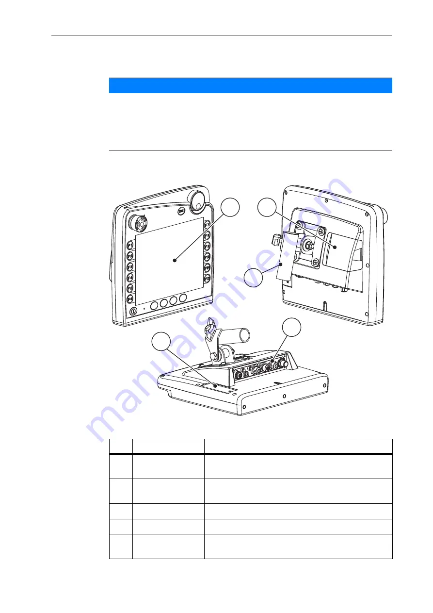
Layout (CCI 100)

Figure 2.1:

Terminal CCI 100 overview

NOTICE

Due to the great variety of different ISOBUS-compatible terminals, the present 
chapter is restricted to the layout and functions of the

 CCI 100

 ISOBUS terminal 

as an example.

Please observe the instructions in the respective operator's manual of your 
ISOBUS terminal.

No.

Designation

Function

1

Control panel

Including foil keys, display, scroll wheel and stop 
switch.

2

USB port with cov-
er

Protects the USB port from dirt. For data exchange, 
task controller and terminal updates.

3

Mounting bracket

For mounting the terminal within the tractor cabin.

4

Terminal strip

Terminal strip for the cables of the ISOBUS system. 

5

Softkey switch

Enables switching the functions from the left to the 
right side of the screen.

1

2

3

4

5

Summary of Contents for Axent Isobus

Page 1: ...s instruction manual assembly in struction is to be considered as part of the machine Suppliers of new and sec ond hand machines are required to document in writing that the instruc tion manual assembly instruction was delivered with the machine and hand ed over to the customer Original instructions 5901646 d en 0716 ...

Page 2: ...provements We are continuously improving our products Therefore we reserve the right to make any improvements and changes to our machine that we consider necessary without notice This constitutes no obligation to make such improvements or changes on machines that have already been sold We will be pleased to answer any other questions that you might have Yours sincerely RAUCH Landmaschinenfabrik Gm...

Page 3: ...n 5 2 1 Layout CCI 100 5 2 2 Control elements CCI 100 6 2 2 1 Overview 6 2 2 2 Touch screen 7 2 2 3 Function keys 8 2 2 4 Scroll wheel 8 2 2 5 Stop switch 9 2 3 Display 10 2 3 1 Description of the operating screen 10 2 4 Library of symbols used 11 2 4 1 Navigation 11 2 4 2 Menus 12 2 4 3 Operating screen symbols 13 2 5 Structural menu overview 15 3 Attachment and installation 17 3 1 Tractor requir...

Page 4: ...r empty 32 4 7 Machine settings 33 4 7 1 Operating mode of fertiliser supply 34 4 7 2 Lime operation 38 4 7 3 Belt speed mm s 39 4 7 4 belt speed 39 4 7 5 Opening the pre metering slides mm 39 4 7 6 Opening adjustment 40 4 7 7 Forward speed calibration 41 4 8 Fast emptying 44 4 9 System test 45 4 9 1 Test diagnosis 46 4 9 2 Service 48 4 10 Info 48 4 11 Weighing Trip counter 49 4 11 1 Trip counter ...

Page 5: ...in automatic operating mode 57 5 2 Loading in manual operating mode 59 5 3 Loading in lime operation 61 6 Alarm messages and possible causes 63 6 1 Meaning of the alarm messages 63 6 2 Clearing an error alarm 64 6 2 1 Acknowledging an alarm message 64 Index A Terms conditions of warranty ...

Page 6: ...Table of Contents IV ...

Page 7: ...used e g g in the tractor The operator s manual does not replace your own responsibility as the operator and operating personnel of the machine control unit AXENT ISOBUS 1 2 Information on the illustration 1 2 1 Significance of warnings The warning instructions in this manual have been structured according to the de gree of danger and the probability of their occurrence Danger signs and symbols in...

Page 8: ...arning warns of a possible dangerous situation for the health of persons Ignoring these warnings will result in very serious injury Always observe the measures described to prevent this danger n CAUTION Type and source of danger This warning warns of a potentially dangerous situation for per sonal health or of material and environmental damage Ignoring this warning can result in injuries and damag...

Page 9: ...ety page 5 References to other documents are indicated as note or instruction without exact chapter or page number Example Please also observe the instructions contained in the manual for the universal drive shaft 1 2 5 Menu hierarchy keys and navigation Menus are the entries listed in the Main menu window In the menus submenus and or menu items are listed in which settings can be implemented sele...

Page 10: ...User instructions 1 4 ...

Page 11: ...ns in the respective operator s manual of your ISOBUS terminal No Designation Function 1 Control panel Including foil keys display scroll wheel and stop switch 2 USB port with cov er Protects the USB port from dirt For data exchange task controller and terminal updates 3 Mounting bracket For mounting the terminal within the tractor cabin 4 Terminal strip Terminal strip for the cables of the ISOBUS...

Page 12: ...s 6 firmly defined 12 freely assignable foil buttons Scroll wheel Stop switch Softkey switch Figure 2 2 Operating panel on the front side of the unit NOTICE For further information on operating the CCI 100 terminal and its control ele ments refer to the enclosed operating manual The operating manual is an in tegral part of the terminal unit 1 2 3 4 5 6 7 8 10 9 2 ...

Page 13: ...sages 4 Information key Freely assignable key Refer to the CCI 100 termi nal operating manual 5 Double arrow key Navigation between the system screens of the ter minal 6 Main menu key Changing to the main menu of the terminal refer to the manufacturer operating manual 7 ON OFF Switching the terminal on off 8 Stop switch The stop switch puts the connected devices into a safe state Not all ISOBUS te...

Page 14: ...pends on the displayed menu screens Functions are generally executed by pressing the function key next to the icon or by pressing the button on the touch screen Function keys without icon do not have any functionality in the respective menu screens 2 2 4 Scroll wheel The scroll wheel is used for fast navigation in the menus as well as for entering or changing data in input fields Turning the scrol...

Page 15: ...ped the comb roller is stopped the hopper cover is stopped Case 2 No spreading operation example calibration fast emptying If no spreading operation is active all functions are stopped and the metering slides remain open A warning message is displayed as soon as the stop switch is actuated 1 Rectify the cause of the fault 2 Unlock the stop switch Another alarm message warning against possible unex...

Page 16: ...ine control unit display 1 9 10 8 13 14 11 12 15 3 4 5 6 2 7 7 1 Left pre metering slide display 2 Large area spreader filling level display 3 Right application rate adjustment 4 Current opening position of right pre meter ing slide 5 Right pre metering slide display 6 Right spreading unit filling level display 7 Function keys 8 Display field Conveyor belt speed 9 Display field Forward speed 10 Di...

Page 17: ...ol unit displays symbols for the individual menus and functions 2 4 1 Navigation Symbol Meaning Go to the left previous page Go to the right next page Back to the previous menu Back to main menu Switching between working screen and menu window Cancellation closing the dialogue window ...

Page 18: ...2 12 2 4 2 Menus Symbol Meaning Change from a menu window directly to the main menu Switching between working screen and menu window Hopper cover Machine settings Fast emptying System test Information Weighing Trip counter ...

Page 19: ...ol The rear cover is open Start loading Start lime spreading Stop lime spreading The pre metering slide can be closed The keep pre metering slide open function is active Selection of the open position for pre metering slide Increase plus pre metering slide opening Decrease minus pre metering slide opening Increase plus conveyor belt speed Terminals with 2x6 function keys only ...

Page 20: ...function 2 14 Decrease minus conveyor belt speed Terminals with 2x6 function keys only Switching between working screen and menu window Pre metering slide open position reset to preset opening value Symbol Meaning ...

Page 21: ... en Hopper cover Machine settings Fast emptying System Test Main menu Working screen Operating mode Belt speed mm s Tractor km h kg level sensor Test Diagnosis Service Rest kg ha m Trip counter km h Weighing Tripcounter Zero scales Meter counter opening Pre metering mm Belt speed ...

Page 22: ...Layout and function 2 16 ...

Page 23: ...ISOBUS 3 2 Connections sockets NOTICE In tractors without load switchable gear the forward speed must be selected us ing the correct transmission ratio in a way that it corresponds to a PTO speed of 1000 U min NOTICE If the tractor is not equipped with a 9 pin socket at the rear a tractor assembly set including a 9 pin socket ISO 11783 be purchased additionally as special equipment NOTICE Check wi...

Page 24: ...the tractor cabin within the driver s field of vi sion to fix the ISOBUS terminal Attach the ISOBUS terminal with the bracket in the tractor cabin NOTICE For details on the connection of the terminal please refer to the operator s man ual of the terminal manufacturer NOTICE Observe the supplied operator s manual of the terminal ...

Page 25: ...sensors controlled by the electronic system Figure 3 1 Overview of actuators and sensors at the AXENT large area spreader 7 8 9 1 Hopper cover 2 Level sensor 3 Vibrator optional 4 Axis angle sensor Rear weigh cells left right Steering cylinder optional Steering axle A B stop valve optional 5 Front weigh cells left right 6 Towing bar angle sensor 7 Hydraulic block with valves 8 Oil temperature sens...

Page 26: ...arge area spreader and AXIS PowerPack fertiliser spreading unit 4 5 6 7 10 11 8 9 3 12 1 Comb roller 2 Belt drive Belt speed sensor 3 Forward speed sensor at right wheel 4 Metering slide actuator right Right agitator 5 Drop point actuator right 6 FAG sensor in hydraulic motor left right 7 Drop point actuator left 8 Metering slide actuator left Left agitator 9 Interface connector for spreading unit...

Page 27: ... V is guaranteed n CAUTION Risk of injury due to ejected fertiliser In case of a fault the metering slide can open unexpectedly during road transport to the spreading location There is a risk of slipping and personal injury due to discharged fertiliser Before leaving for the place of spreading the electronic machine control unit AXENT ISOBUS must always be switched off NOTICE The operator s manual...

Page 28: ...er is important safety equipment for safe machine operation Loading cannot be realized if the rear cover is open The rear cover is equipped with a switch The switch reports the open or closed position of the rear cover to the machine control unit If the rear cover is open all actuators controlled via the machine control unit are stopped conveyor belt pre metering slide comb roller hopper cover NOT...

Page 29: ...e rear cover Please refer to the operator s manual of the machine 2 Press the ACK key The alarm message is acknowledged and disappears As long as the rear cover is open the warning symbol is displayed in the top of the operating screen ...

Page 30: ...g the sub menu via the touch screen 1 Press the button of the desired sub menu Windows appear prompting various actions Text input Value input Settings made in further sub menus NOTICE Please refer to chapter 1 2 5 Menu hierarchy keys and navigation page 3 for important notes regarding the display and navigation between menus In the following accessing menus and menu items by touching the touch sc...

Page 31: ...hine settings adjustments at the attached spreading unit can be realized simultaneously The ISOBUS terminal enables switching between the two ma chine control units AXENT ISOBUS and AXIS H ISOBUS The following settings are recommended to switch between screens during spreading Requirement The implement ECUs are registered at the ISOBUS terminal with the follow ing versions AXENT ISOBUS version 2 0...

Page 32: ...eration AXENT ISOBUS 4 26 2 Open the User settings menu Figure 4 2 User settings menu of the ISOBUS terminal 3 Select Free button assignment in the selection list 4 Mark the Fertiliser entry 5 Press OK 1 ...

Page 33: ...ype U2 Figure 4 3 Transmission of fertiliser settings from AXIS H ISOBUS 1 Spreading disc type U2 for lime spreading unit 2 Application rate 3 Working width 4 Flow factor The application rate 2 the working width 3 and the flow factor 4 are transferred automatically at the AXENT ISOBUS machine control unit If the application rate at the lime spreading unit is incorrect the flow factor can be adjust...

Page 34: ...pening closing the hopper cover Page 29 Machine settings Tractor and large area spreader settings Page 33 Fast emptying Direct access to menu for fast emptying of the large area spreader Page 44 System Test Settings and diagnosis of the machine control unit Page 45 Info Display of machine configuration Page 48 Weighing trip count values regarding spreading work carried out and functions for weighi...

Page 35: ...ning and can cause per sonal injury Ensure that nobody is present in the hazard zone NOTICE The menu is only used for activating the valves to open or close the hopper cov er The machine control unit AXENT ISOBUS does not detect the exact position of the hopper cover Observe the movements of the hopper cover n CAUTION Material damage due to insufficient clearance Opening and closing the hopper cov...

Page 36: ...EN direc tion 2 Release the function key Operation of the valve is stopped The hopper cover is stopped 3 Fill in fertiliser 4 Keep the function key pressed until the hopper cover is fully closed During the movement an arrow appears which indicates the CLOSED di rection 5 Release the function key Operation of the valve is stopped NOTICE Keep the function key only pressed as long as necessary Otherw...

Page 37: ...nd the attached AXIS Power Pack or LIME PowerPack spreading unit 4 6 1 Spreading material supply The AXENT conveyor belt is started up with opening of the AXENT pre metering slides The spreading material is discharged through the outlet into the AXIS PowerPack or LIME PowerPack spreading unit Figure 4 6 Open pre metering slide display 1 Open pre metering slide 2 Standing conveyor belt 3 Running co...

Page 38: ...ning spreading material in the hopper is usually sufficient for a few loading operations Despite the alarm message the AXENT ISOBUS machine control unit attempts full loading of the residual quantity Figure 4 7 AXENT hopper filling level indicator NOTICE The filling level sensor does not have a function if the kg level sensor is active See Machine settings on page 33 ...

Page 39: ...enu windows tab Sub menu Meaning Description Operating mode Definition of the operating mode Manual Automatic Lime AUTO km h Page 36 opening Pre setting of the opening adjust ment for pre metering slide No function in lime operation To be entered in a separate input win dow Pre metering mm Opening adjustment of pre metering slides No function in lime operation To be entered in a separate input win...

Page 40: ...trols the valves for fertil iser supply according to sensor information Start in Manual operating mode and stop loading by pressing the Activation key The sensor conditions signal the required steps Belt speed mm s Conveyor belt speed setting Page 39 No function in lime operation Tractor km h Definition or calibration of the speed signal Page 41 kg level sensor Input of the residual quantity to tr...

Page 41: ...the list 4 Press OK Automatic Figure 4 10 Operating screen in automatic 1 Symbol of active automatic operating mode 2 Spreading operation active n WARNING Danger of crushing and shearing due to components operat ed by an external force The pre metering slide and the conveyor belt move without warn ing and may lead to personal injury Ensure that nobody is present in the hazard zone 1 2 ...

Page 42: ...age due to ejected fertiliser Activate the Manual operating mode If loading is active overflow in the fertiliser spreader may occur and excessive fertiliser may leak unexpectedly from the hopper Persons may slip and be injured Risk for the environment Continuously check manual loading during spreading oper ation The manual operating mode is only to be used temporarily in exceptions Use automatic o...

Page 43: ...d and loading is stopped manually 1 Press the Start loading key Loading is started Loading is realized in the same order as for the automatic operating mode 2 Press the Start loading key Loading is stopped See also 5 2 Loading in manual operating mode page 59 ...

Page 44: ... Machine Open Settings Operating mode 2 Select the Lime AUTO km h menu entry The bottom menu entries do not have any function Figure 4 12 Operating screen in lime operation 1 Symbol of active lime AUTO km h operating mode 2 Spreading operation start NOTICE Application rate working width and flow factor for lime operation are set via the AXIS H ISOBUS machine control unit Observe the operator s man...

Page 45: ...nt 1 Open the Machine settings belt speed mm s menu 2 Enter the value of the speed adjustment 3 Press OK 4 7 5 Opening the pre metering slides mm In this menu the pre metering slide opening can be defined During operation the pre metering slide opening can be adjusted in the operating screen 1 Open the Machine settings Pre metering slide mm menu 2 Enter the value from the fertiliser chart 3 Press ...

Page 46: ...ide opening serves as basis 100 Defining the opening adjustment 1 Open the Machine settings opening menu 2 Enter the percentage by which the opening is to be adjusted 3 Press OK NOTICE During operation the Opening Opening function keys can be used to adjust the pre metering slide opening by the Opening factor at any time The pre configuration can be restored with the C 100 key ...

Page 47: ...n on the field This reduces the influence of the ground characteristics on the calibration result Determine a 100 m long reference track as precisely as possible Fill only half of the machine if possible Opening the speed settings In the AXENT ISOBUS control unit you can save up to 4 different profiles for the type and number of pulses You can assign names to these profiles e g trac tor name Befor...

Page 48: ...le 1 Tractor type name field 2 Display of number of pulses over 100m 3 Confirm the profile selection 4 Delete profile 2 Open Name field 1 3 Input the name of the profile Entering text into the control unit is described in section 4 12 1 Text input page 53 4 Press OK 3 The profile is active NOTICE The input of the name is restricted to 16 characters We recommend using the profile with the name of t...

Page 49: ... 1 Text input page 53 If the exact pulse count is unknown a calibration has to be started 6 Press the calibration key in the tractor profile The calibration operating screen is displayed 7 Press Start at the starting position of the reference distance The pulse display is now on zero The control unit is ready for counting pulses 8 Drive along the 100m long reference distance 9 Stop tractor at the ...

Page 50: ...S in this condition This prevents accumulation of humidity in the hopper Carrying out the fast emptying process 1 Open the Main menu Fast emptying menu Figure 4 15 Fast emptying menu 1 Metering slide opening display 2 Press Start Stop The fast emptying process starts 3 Press Start Stop once the hopper is empty Fast emptying is complete NOTICE Before starting the fast emptying process it is to be e...

Page 51: ...gs for the machine control unit can be con figured Open the Main menu System test menu Figure 4 16 System test menu Sub menu Meaning Description Test diagnosis Checking of actuators and sen sors Page 46 Service Service settings Password protected only accessible to service per sonnel ...

Page 52: ...ing closing the pre metering slides Checking the calibration Belt drive Manual operation of the conveyor belt Sonic sensor Checking the sensors in fertiliser spreading unit hopper AXENT level sensor Checking the level sensor in the AXENT hopper Oil reservoir Checking the oil temperature and the oil level Hopper cover Test function for opening clos ing the hopper cover Valve condition Sensor cover ...

Page 53: ...test Test diagnosis menu 2 Press the left right arrows to navigate to the Sensor cover page The display shows the actuator sensor status Figure 4 17 Test diagnosis example Sensor cover 1 Signal display 1 Rear cover is closed 0 Rear cover is open 2 Bar graph signal 1 2 ...

Page 54: ...or with the scroll wheel 4 Press Start Stop The test for control of the selected equipment is started 5 Press Start Stop again The test is completed 4 9 2 Service 4 10 Info The Info menu provides information on the control unit NOTICE An input code is required to adjust the settings in the Service menu These set tings can only be modified by authorised service personnel NOTICE This menu provides i...

Page 55: ...eaning Description Trip counter Only for lime operation Display of the ap plied spreading quantity area spread and spread distance Page 50 Rest kg ha m Only large area spreader with weighing function Display of the residual quantity in the hopper Page 51 Metre counter Display of the distance travelled since the last reset of the meter counter Reset zero ing by pressing C 100 Zero scales Only large...

Page 56: ... During the spreading work i e with the metering slides being open you can change into the Trip counter menu and obtain the current values there Figure 4 20 Trip counter menu 1 Spread quantity area and distance display fields 2 Clear trip counter entry Delete trip counter 1 Open the Weighing Trip counter Trip counter sub menu The calculated values for spread quantity area and distance since the la...

Page 57: ... counter Rest kg ha m menu The Rest menu appears The residual quantity is displayed Figure 4 21 Rest menu 1 Residual quantity display in kg 2 Application rate working width possible spread area and distance display fields NOTICE The display of residual quantity is only possible for machines with weighing func tion If the large area spreader is not equipped with weigh cells this menu has no functio...

Page 58: ...machine is at a standstill the machine is in a horizontal position and off the ground the support stand is retracted the PTO shaft is switched off the tractor is at a standstill 1 Open the Weighing Trip counter Zero scales menu 2 Press the Zero scales button The weighing value for the empty scales is now set to 0 kg Figure 4 22 Weighing Trip counter menu NOTICE Tare the scales before each use in o...

Page 59: ...s purpose 2 dif ferent input windows are displayed Figure 4 23 Alphanumerical input Figure 4 24 Numerical input 1 Enter the desired text or the desired value via the keyboard 2 Press OK The text will be stored in the machine control unit The previous menu is displayed 3 Cancel the input by pressing the ESC key Back to the previous menu ...

Page 60: ... menus include selection windows Figure 4 25 Selection window 1 Select the desired entry in the selection window 2 Press OK The selection will be stored The previous menu is displayed 3 Cancel the input by pressing the ESC key The previous menu is displayed ...

Page 61: ...rent ISOBUS compatible terminals the present chapter is restricted to the layout and functions of the CCI 100 ISOBUS termi nal Please observe the instructions in the respective operator s manual of your ISOBUS terminal Menu value Conversion factor metric to imperial kg Rest 1 x 2 2046 lb mass lbs rest ha Rest 1 x 2 4710 ac ac rest Working width m 1 x 3 2808 ft Application rate kg ha 1 x 0 8922 lbs...

Page 62: ...Operation AXENT ISOBUS 4 56 ...

Page 63: ...ve See Automatic page 35 NOTICE The sensor conditions and loading can be observed on the operating screen However the messages are displayed without sound Function control Operating screen display The loading function is active One of both level sensors LLST or LRST reports empty Open the pre metering slides The conveyor belt starts up simultaneously Fertiliser flow runs into the spreading unit ho...

Page 64: ...ntrol unit 5 58 The overflow is reached The conveyor belt is stopped The pre metering slides remain open Loading is completed Press the loading key at the end of work Close the pre metering slides Function control Operating screen display ...

Page 65: ...ode is selected See Operating mode selection page 35 The spreading operation is started Function control Operating screen display One of both level sensors LLST or LRST re ports empty Press Start loading Loading is active Open the pre metering slides The conveyor belt starts up simultaneously Fertiliser flow runs into the spreading unit hopper Adjust the conveyor belt speed and the open ing of the...

Page 66: ...with AXENT ISOBUS machine control unit 5 60 The overflow is reached Press Start loading The conveyor belt is stopped Close the pre metering slides Loading is completed Function control Operating screen display ...

Page 67: ...th machine control units page 27 Function control Operating screen display Press Start loading Loading is active Start spreading The speed of the conveyor belt and the pre metering slide opening are automatically ad justed to the forward speed Press Start loading in the headlands The conveyor belt is stopped The pre metering slides remain open Press Start loading again during travel into the field...

Page 68: ...Loading with AXENT ISOBUS machine control unit 5 62 ...

Page 69: ...loaded The machine is overloaded The load inside the machine exceeds 10 000 kg Manual mode active Risk of fertiliser overflow The message is displayed on switching over from auto matic to manual Cover open Switch is not operated the loading function is not possi ble The rear cover is open and not properly closed Stop loading The message is displayed on switching over to the sys tem test menu durin...

Page 70: ...alarm message is highlighted in the display and displayed with a warning sym bol Figure 6 1 Alarm message example 1 Correct the cause of the alarm message Please observe the operator s manual of the machine and section 6 1 Mean ing of the alarm messages page 63 2 Press the ACK key The alarm message is cleared ...

Page 71: ...8 K Key ACK 23 64 Menu 24 L Level sensor 46 Lime functions Test 48 Lime operation 33 61 Lime settings 28 M Machine control unit Actuators and sensors 19 Alarm message 63 Attachment 17 Connection 17 18 Display 10 Mounting bracket 18 Software version 21 Status indicator 31 Structure 5 Machine settings 28 Belt speed 33 Lime operation 33 Manual operating mode 33 36 Pre metering slide opening 33 Main m...

Page 72: ...version 21 Speed Calibration 41 Signal source 42 Status indicator AXENT hopper 32 Symbols Library 11 13 Menus 12 Navigation 11 Operating screen 13 System test 28 45 46 Service 45 Test diagnosis 45 T Tare the scales 52 Terminal activation 21 See machine control unit Test diagnosis 45 46 Hopper cover 46 Level sensor 46 Lime functions 48 Oil reservoir 46 pre metering slide 46 Rear cover 46 47 Voltage...

Page 73: ...ng manual must be observed In all cases of doubt contact our sales representatives or the factory directly Warranty claims must be submitted to the factory by 30 days at the latest after occurrence of the problem The date of purchase and the serial number must be indicated If repairs under the war ranty are required they must be carried out by the authorised workshop only after consultation with R...

Page 74: ......

Reviews: