background image


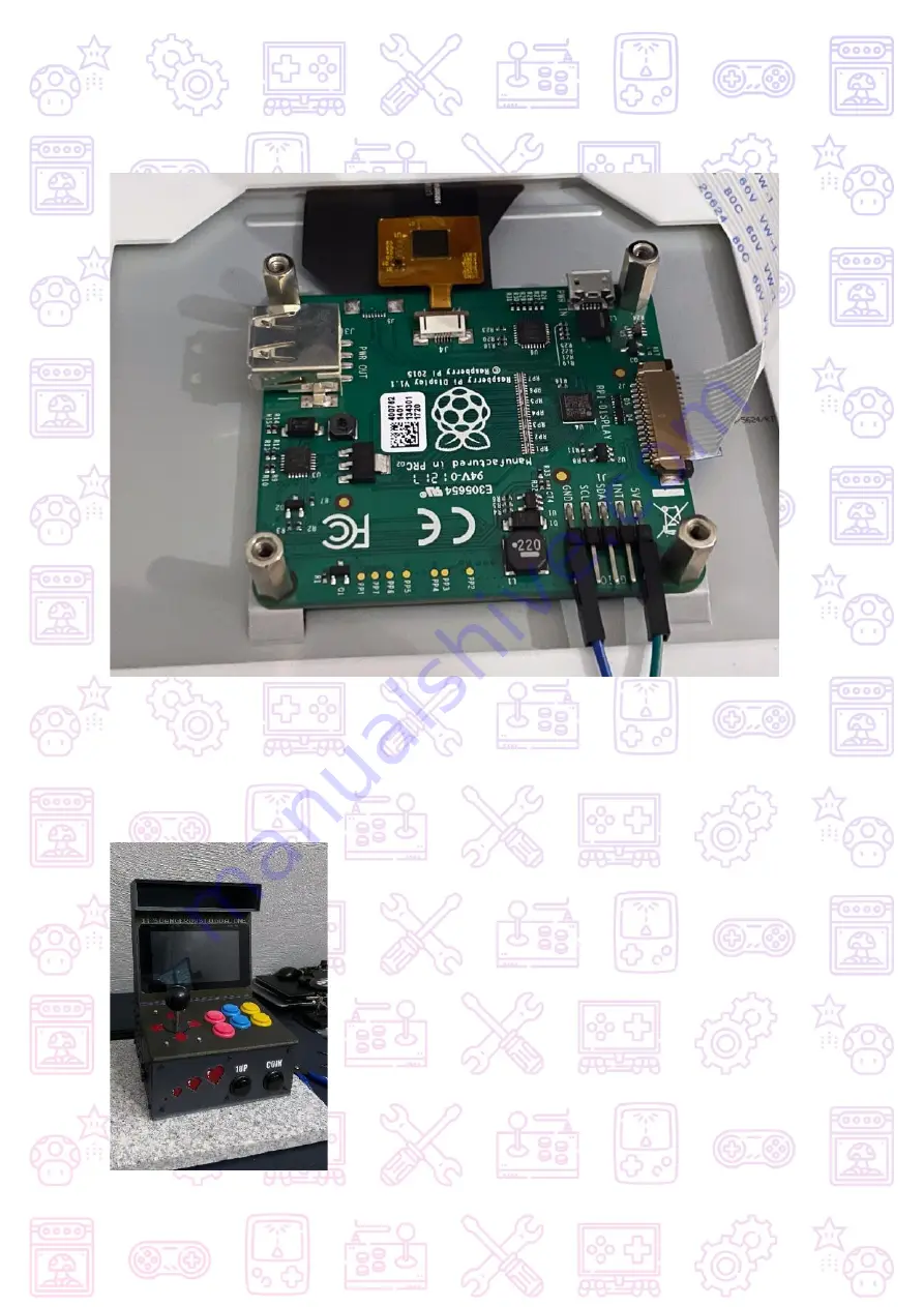
Take the Display Part and connect the Flat-Cable to the Display. The Contacts should be 
facing to you. Connect the Power Cable to the Pin-Header (GND and 5v)


Now push in the Display to the Case. Start on the Top and take care of the cables not to 
slip in between. Then push fit on the bottom. If its too lose use the neodymium magnets to 
hold the Display in Place. 

Now it should look something like this: 


Summary of Contents for PICADE 3D

Page 1: ......

Page 2: ...TableofContents 1 BOM 2 PreflightCheck 3 Preparations 4 Assembly 5 OptionalFeatures 6 Software...

Page 3: ...at Pimoroni or DIY 1x Arcade Parts Kit Pimoroni or 1x Retro Joystick 10X Arcade Buttons 2xBlue 2xYellow 2xRed 4xBlack 1x Set of Cables eq Pimoroni Wiring Loom or DIY 1x On Off Button with or without i...

Page 4: ...x20 12x M3 Washers 8x M3 Nuts 4x RubberFeet Fancy Lights LED Strip or Neopixel Bars to Put behind the FrameBar for Cool Effects Filament 1 1 5 Kg for the Complete Build depends on Print Settings Recom...

Page 5: ...nted Parts 1 Baseplate 6 Cover_Backpanel Light_Tunnel 2 LeftPanel 7 Display_Frame 3 RightPanel 8 Display_Top 4 FrontPanel 9 Joystick_Button 5 Backpanel 10 LightSign Backpanel_noHDMI or Backpanel_HDMI...

Page 6: ...1 9 5 8...

Page 7: ...Bolts etc 6 Picade X Hat 11 Joystick 2 Magnets 7 Speaker 12 Buttons 3 Fan 8 On Off Button 13 Wires 4 Raspberry Pi 9 7 Touch Display 14 Controller 5 Micro SD Card 10 LightStrip NeoPixel 15 MicroHDMI HD...

Page 8: ...11 12 13 14 15...

Page 9: ...Tools you will need 1 Allen Key Superglue 2 Tweezer Wires or Jumper Wires 3 Solder Iron 4 Deburring Tool 5 Side Cutter 3 5 2 1 4...

Page 10: ...te the Image tot he Micro SD Card For Windows Raspberry Pi Imager Etcher or Win32DiskImager Win32DiskImager requires an img file extracted from the img gz image downloaded You can use a program like 7...

Page 11: ...own in the Template to ensure that the RetroPie Setup wifi configuration module will be able to cleanly edit delete your configuration if you wish to change it later Hint Wifi will not start up if you...

Page 12: ...e Assembly its neccessary to prepare our Printed Parts with the threaded inserts So its time to fire up your solder iron and get those Inserts melted in We need the following Parts Baseplate Back Pane...

Page 13: ...Go on with the Back Panel with two Inserts for the Cover...

Page 14: ...The Joystick_Button Part gets a total of 5 Inserts...

Page 15: ...The Last Part Display_Top takes another 6 Inserts 2 on each side Attention Do not hurry on these steps as the Tolerances are very tight and you get in Trouble if the Inserts are not Lined Up correctly...

Page 16: ...ep we need all the Panels If you chose the HDMI Backplate we prepare this as well and the Button_Joystick Part The Buttons have a tight fit and do not clip in fully in Case you wonder The Tight fit is...

Page 17: ...the M3 Bolts for the Speaker and turn over the part Arrange the Speaker on the Bolts and put on the Washers if your Screws are long enough otherwise screw on the nuts with the help of a tweezer to tig...

Page 18: ...The Left Panel is holding our Power Button Prepare it with the Wires before and screw it on tight Wiring depends on the Type of Button...

Page 19: ...For the Joystick Part we need all the leftover Buttons and the Joystick Clip in the Buttons like on the other Parts and take the M3x20 screws Washers and Nuts...

Page 20: ...ut in the Screws and Flip over the Part to align the Joystick part with the connector near to the Buttons Pro Tip Take some Tape to hold the Screws in Place and to Prevent Falling off when Flippin ove...

Page 21: ...not tighten them full Flip over and adjust the Joystick to be centered in the Hole After that tighten the screws Now put on the DustCover and Screw on the Big Joystick Ball So lets start with the fun...

Page 22: ...spberry Pi s here In this Step we are going to bring our Raspberry and the Picade Hat X in Place Dont forget the Fan to cool down the Pi This is essential because the Pi is getting really hot when emu...

Page 23: ...h on the GPIO Panel as the Board may collide with the Heatsink which can produce a short Leave a 1mm gap between those Kapton or Isolation Tape is also Recommended Check if you have inserted the Micro...

Page 24: ...aration To Prepare our Display we need 4x M3 Screws and 4 Washers Optionally 8 Neodym Magnets if you want to hold the Display in the Case when its not tight fit Put in the Display so the USB port is l...

Page 25: ...ws are longer so you don t damage the screen Don t tighten them fully Adjust the Display so it fits and then tighten one screw after the other If you need the Magnets just glue them into the holes Wat...

Page 26: ...eded its time to assemble everything First we start with the Backplate and the Side Panels Screw in all the Bottom Screws Do not overtighten Plug in the micro hdmi cable into port 0 HDMI0 if you choos...

Page 27: ...Buttons to the Picade X Hat Take the 4x Pair Cable from the Wiring Loom Kit and connect the Buttons to the correct Plugs on the Picade Utility Header Also Plug in the Power Button Be aware to the Pola...

Page 28: ...a additional Cable to Power your Light Strip Its Recommended to build a Y Cable for this Take some Jumper Wires and solder them together like this The Male Wires go into the Picade Hat and connects t...

Page 29: ...h some 3M Tape or Double Sided Tape Leave the Cable long enough and put some JST Connectors on it for clean cabling At the Moment of this Manual i used some ATTiny USB to power the Lights Feel free to...

Page 30: ...ts important that the insert nuts are placed very well Halfway done Grab the Joystick and Button Part an lay it upside down so you can connect the cables easily First connect the Joystick Cable and ma...

Page 31: ...nect the Cables like its printed on the Picade Hat Be sure to Check the GND Pin on the Joystick Cable Put back on the Top Part in case you removed it Grab the display cable and the power cable through...

Page 32: ...ou Connect the Power Cable to the Pin Header GND and 5v Now push in the Display to the Case Start on the Top and take care of the cables not to slip in between Then push fit on the bottom If its too l...

Page 33: ...Light Tunnel Part Printed in Black Filament to Prevent Light Bleeding If the LED_SignPart is too loose Take some drops of SuperGlue not much in case you have to detach it In the Last step screw on the...

Page 34: ...If you see something on the Screen Congratulations You made it To calibrate the Buttons and Configure Retropie Head over to https retropie org uk docs...

Page 35: ...he Picade X Hat refer to https github com pimoroni picade hat For more Information about Retropie visit https retropie org uk Donations https www paypal me andre1289 Questions or Feedback Welcome andr...

Reviews: