

I/O Bank Voltage Select Jumper Links
Make sure the two jumper links that select the GPIO bank 0 and 1 voltages are present on header J3
(and set to the voltage you wish to use).
Do not power up the board if these jumpers are not in
place (and hence the GPIO bank(s) are unpowered) as this may damage the module.
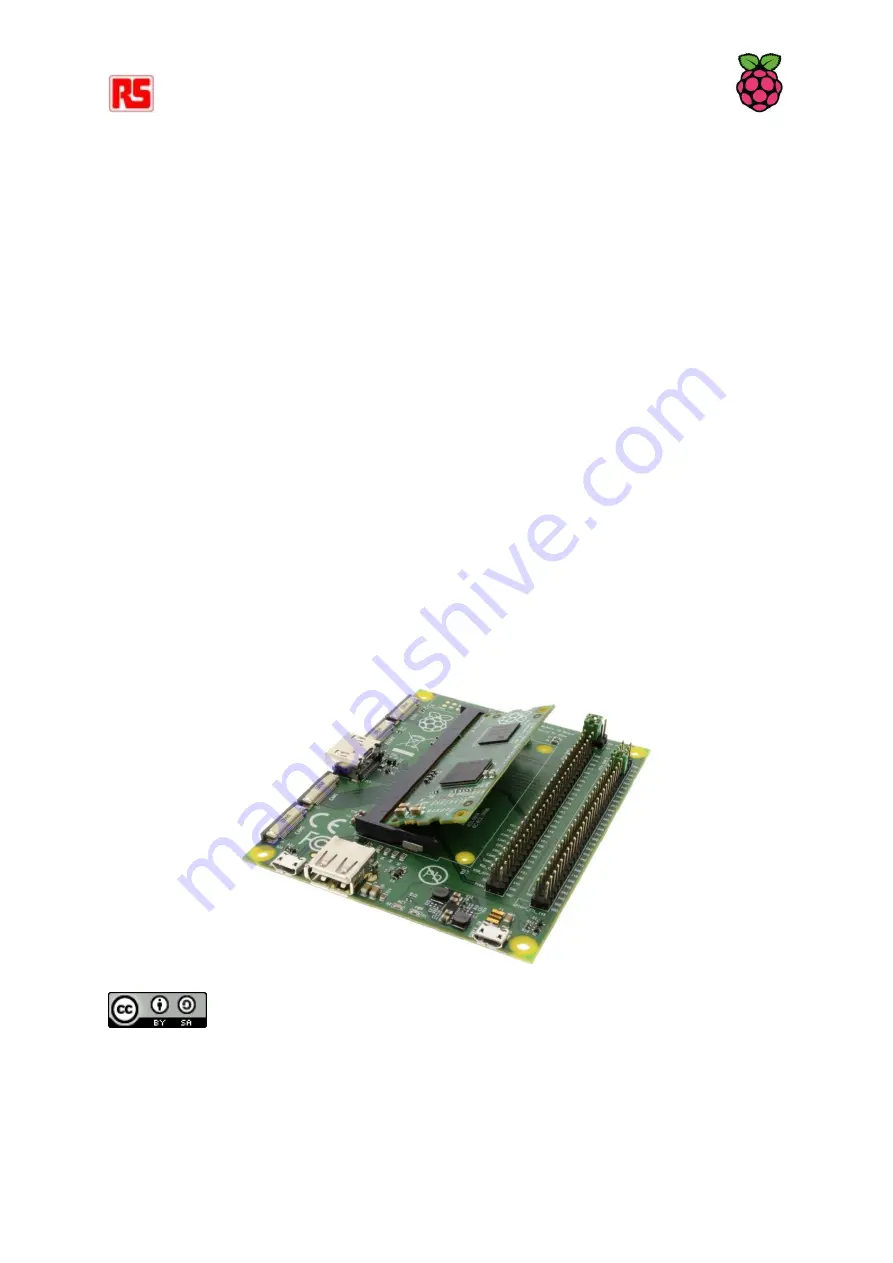
Powering Up
Check the Compute Module is inserted correctly into socket J1. Make sure the GPIO Banks are
powered (Check J3 has jumpers present and set correctly). Attach the micro USB power supply cable
to socket J2 (POWER IN) to power up the board.
At this point the red POWER and green ACT LEDs should light up. Nothing further should happen as
the Compute Module Flash memory [eMMC] is supplied blank and awaits an Operating System of
your choice.
Loading an OS Image and Further Documentation
The next step is to write an Operating System (OS) image to the on-board eMMC Flash memory.
Once this is done the board should boot into the OS at power on.
Further documentation including a step by step guide to Flashing the eMMC is available here:
http://www.raspberrypi.org/documentation/hardware/computemodule/
or download the
Compute Module Hardware Design Guide from:
http://uk.rs-online.com/web/p/products/8134164/
Raspberry Pi Documentation
by the
is licensed under a
Attribution 4.0 International License


