Raptor OW1.7-VS-CL-LP-640 User Manual Download Page 4

OW1.7-VS-CL-LP-640 / USER MANUAL REV1 
November 2017 

4


2.


SPECIFICATION 

2.1 

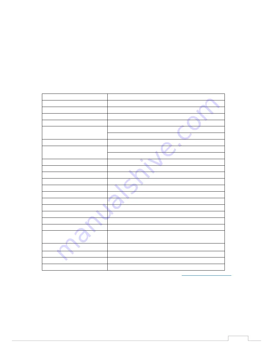
Camera Specification 

The  OWL  Mini  digital  camera  is  designed  for  high-resolution  applications  requiring  visible  to  SWIR 
imaging (400-1700nm).  The OWL M camera uses an InGaAS sensor with a resolution of 640 x 512 in a 
14-bit digital output.  High-speed low-noise electronics provide linear response and sensitivity for rapid 
image capture.  

The Camera Link digital interface provides the most stable platform for data transfer and the camera 
will work on any Camera Link standard card.  

A Software Development Kit (SDK) is available for interfacing with custom software. 

Sensor Type 

InGaAs PIN-Photodiode 

Active Pixel 

640 x 512 

Pixel Pitch 

15μm x 15μm  

Active Area 

9.6mm x 7.68mm 

Spectral response1 

0.4μm to 1.7μm 

Noise (RMS) 

<195 electrons Low Gain (176 electrons typical) 
<50 electrons High Gain (40 electrons typical) 

Quantum Efficiency 

Peak >92% (>87% @ 1.064nm, 82% @ 1.55nm) 

Pixel Well Depth 

Low Gain: 650Ke- 
High Gain: 12Ke- 

Pixel Operability 

>99.5% 

Digital Output Format 

14 bit Camera Link (Base Configuration) 

Exposure time 

1μs to 1 / frame rate 

Shutter mode 

Global shutter 

Frame Rate 

Up to 120Hz programmable 

Optical Interface 

C mount 

Camera Setup / Control 

Camera Link 

Trigger interface 

Trigger IN and OUT - TTL compatible 

Power supply 

12V DC ±10% 

TE Cooling 

None 

Image Correction 

3 point NUC (offset, Gain & Dark Current) + pixel correction 

Functions controlled by serial 
communication 

Exposure, intelligent AGC, Non Uniformity Correction, 
Gamma, Pk/Av, TEC, ROI 

Camera Power Consumption 

< 2.5W 

Operating Case Temperature 

-20°C to +55°C 

Storage Temperature 

-30°C to +60°C 

Dimensions & Weight 

42mm x 42mm x 67mm / 170g 

Latest version available on 

www.raptorphotonics.com


Summary of Contents for OW1.7-VS-CL-LP-640

Page 1: ...OWL Mini Model OW1 7 VS CL LP 640 USER MANUAL...

Page 2: ...OW1 7 VS CL LP 640 USER MANUAL REV1 November 2017 2 CONTENT CONTENT 2 1 INTRODUCTION 3 2 SPECIFICATION 4 3 GETTING STARTED 6 4 EPIX XCAP 9 5 MICRO MANAGER 19...

Page 3: ...ss window between the camera sensor and the microscope or lens Should any other issues occur please contact your local agent To clean the sensor window gently wipe the face of the sensor window with a...

Page 4: ...ectral response1 0 4 m to 1 7 m Noise RMS 195 electrons Low Gain 176 electrons typical 50 electrons High Gain 40 electrons typical Quantum Efficiency Peak 92 87 1 064nm 82 1 55nm Pixel Well Depth Low...

Page 5: ...OW1 7 VS CL LP 640 USER MANUAL REV1 November 2017 5 2 2 Mechanical Outline 3D drawings STEP are available upon request...

Page 6: ...o Microscope The OWL 640 has a standard C Mount that should easily screw onto any microscope port 3 3 Mounting to a tripod or optical table The camera has a 20 BSW Whitworth threaded hole to mount to...

Page 7: ...on III Eagle Owl 320 Owl 320 High Speed Owl Mini Owl 640 Ninox 640 Owl 1280 In this guide there is a quick overview of XCAP http www epixinc com support files php and Micro Manager https micro manager...

Page 8: ...light up Boot up the computer Use the Camera Link cable to connect the camera to the computer Connect the other end of the Camera Link cable to the camera Carefully thread the C mount lens onto the c...

Page 9: ...for the latest cameras and latest PIXCI imaging boards Open the downloaded file when complete and follow the onscreen instructions Be sure to accept the board driver installation 4 2 Operating your ca...

Page 10: ...reflect your chosen camera For example for the Owl 640 it should read EPIX PIXCI E8DB Raptor Photonics OWL CL 640 If not you need to select a different camera 8 Check that the camera is communicating...

Page 11: ...Figure 5 Image Capture 12 You should now see an image On the bottom of the screen you should see something similar to the following Frame 0 Size 640 x 512 Resize 0 7x0 7 Video 26 0fps Capture 26 0 fp...

Page 12: ...window of the EPIX software 4 4 Exposure Click on the Gain Tab There is an option for Auto Level Control ALC When Auto Level Control is unchecked you can manually adjust the exposure and digital gain...

Page 13: ...igure 8 Trigger Tab 4 6 Auto On this Tab you can select the parameters for the Automatic Level Control Including the speed and spread of signal taken into account In this mode the FPGA of the camera w...

Page 14: ...s position By default this will be set to account for the whole image Edit the values of Offset Width and Height to place the Auto Level Control ROI over the image Figure 10 Auto ROI Tab Figure 11 Act...

Page 15: ...the exposure but the box becomes too dark to see any detail This is an extreme example used to illustrate this feature 4 8 NUC On this tab you can select the parameters for the on board Non Uniformit...

Page 16: ...ber 2017 16 Figure 14 NUC Off Figure 15 NUC On 4 9 TEC Thermoelectric Cooling TEC Use this tab to set and read back the sensor temperature The optimum temperature should be set on start up for the OWL...

Page 17: ...such that dark areas in the image will appear bright by checking the video invert box Figure 17 Camera Information Output video can be digitally processed to provide image sharpening by checking the...

Page 18: ...the best display of the RAW image data from the camera 1 Go to the Modify Contrast Modification menu Figure 19 2 Select Stretch Contrast Histogram Percentile Endpoints and Preview Figure 20 Stretch Co...

Page 19: ...l package available for Windows Mac and Linux it is easy to install and configure right out of the box with built in functionality and user interface for most common tasks performed in a Life Science...

Page 20: ...ne by going to the downloads section of their website www Micro Manager org You should select the latest nightly build for your operating system found in the Download Nightly Builds section This will...

Page 21: ...ng Micro Manager for the first time you will see the window shown in Figure 22 You need to make sure none is selected then click Ok Figure 22 Hardware Configuration 1 Start the Hardware Configuration...

Page 22: ...en look for the camera driver in the RaptorEPIX folder shown in Figure 24 now click Next Figure 24 Add a New Device 3 Continue to click Next until you are faced with the screen shown in Figure 24 4 Re...

Page 23: ...ember 2017 23 The connected camera should now be recognized Next time you open Micro Manager you can simply select the saved Raptor Owl 640 cfg from the drop down menu figure 26 then click Ok Figure 2...

Page 24: ...ER MANUAL REV1 November 2017 24 5 3 Operating your camera using Micro Manager Figure 27 Opening Screen 1 Click on snap Figure 27 for Micro Manager to open the viewing window as shown in Figure 28 Figu...

Page 25: ...Camera settings All of the camera parameters are controlled within the Device Property Browser this can be accessed by selecting Tools from the menu bar then Device Property Browser Figure 29 Camera...

Page 26: ...7 VS CL LP 640 USER MANUAL REV1 November 2017 26 CORPORATE HEADQUARTERS Raptor Photonics LTD Willowbank Business Park Larne Co Antrim BT40 2SF Northern Ireland PH 44 2828 270141 www raptorphotonics c...

Reviews: