CGTH I
NSTALLATION
, O
PERATION
AND
S
ERVICE
M
ANUAL
42 of 55
2. When the motor approaches nominal r
u
nning
speed, the press
u
re s
w
itch closes and acti
v
ates
the ignition mod
u
le
w
hich in t
u
rn initiates the
p
u
rge.
3. The ignition mod
u
le then energizes the spark
igniter.
4. When sparking
b
egins, the gas
v
al
v
e is ener-
gized.
5. If a flame is detected, the gas
v
al
v
e remains
open. When the call for heat is satisfied, the sys-
tem control mechanism de-energizes and the
gas
v
al
v
e is t
u
rned off.
6. If no flame is detected, the gas
v
al
v
e is closed,
and a p
u
rge period
b
egins. After the p
u
rge
period, the ignition mod
u
le energizes the spark
igniter and the gas
v
al
v
e. If a flame is still not
esta
b
lished, a third and final p
u
rge/ignition
seq
u
ence is
b
eg
u
n. After three failed attempts,
the system control mechanism
w
ill lock o
u
t for a
period of one ho
u
r or
u
ntil the
u
nit is reset.
7. Reset is accomplished
b
y remo
v
ing po
w
er from
the heater for at least fi
v
e seconds.
8. With a three-try mod
u
le,
w
hen the flame is
esta
b
lished and then lost on the first or second
trial, the gas
v
al
v
e
w
ill a
u
tomatically t
u
rn off. A
p
u
rge and trial for ignition
w
ill then occ
u
r.
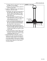
12.4 Testin
g
Esta
b
lish that a satisfactorily p
u
rged gas s
u
pply and
an electrical s
u
pply is a
v
aila
b
le to the heater.
With the gas s
u
pply t
u
rned off at the gas
v
al
v
e, and
the electrical s
u
pply isolated
b
y s
w
itching off at the
local s
w
itch and remo
v
ing the appliance electrical
pl
u
g, open the control cham
b
er sec
u
red
b
y the fo
u
r
scre
w
s. Remo
v
e the sealing scre
w
from the o
u
tlet
press
u
re tap
w
ith a 3/16" Hex Key Allen Wrench and
install a test tap and hose. Remo
v
e the co
v
er cap
from the reg
u
lator scre
w
w
ith a straight slot scre
w
-
dri
v
er thro
u
gh the top hole of the
bu
rner.
T
u
rn on appliance gas
v
al
v
e and connect appliance
electrical pl
u
g. Ens
u
re that the timer or thermostat, if
fitted, is set to call for heat. S
w
itch on po
w
er at the
local s
w
itch. If necessary, the seq
u
ence as descri
b
ed
a
b
o
v
e, in the first and second paragraphs, sho
u
ld
take place. If not, refer to detailed fa
u
lt finding
seq
u
ence. When flame is esta
b
lished, check the gas
press
u
re reading and adj
u
st if necessary. See data
la
b
, Section 2, for req
u
ired gas press
u
re
setting.
Check the gas press
u
re at the o
u
tlet of the gas
v
al
v
e
to ens
u
re minim
u
m press
u
re.
, for req
u
ired gas press
u
re settings.
S
w
itch off the electrical s
u
pply (sh
u
tting do
w
n the
heater), remo
v
e press
u
re ga
u
ge and refit pl
u
g at o
u
t-
let press
u
re tap, ens
u
ring a tight gas seal. Replace
cap and reg
u
lator scre
w
. Close
bu
rner side co
v
er.
FIGURE 37: Pressure Testin
g
Out
le
t
Pre
ssu
re
T
ap
C
o
v
er Cap and
R
e
g
u
la
t
o
r S
c
rew
Summary of Contents for CGTH-30
Page 2: ......
Page 4: ......
Page 6: ......
Page 52: ...CGTH INSTALLATION OPERATION AND SERVICE MANUAL 46 of 55 FIGURE 38 Manometer Reading ...
Page 60: ...CGTH INSTALLATION OPERATION AND SERVICE MANUAL 54 of 55 ...
Page 62: ......
Page 63: ......
Page 64: ......


