


31
WARNING – SERVICING TO BE CARRIED OUT ONLY BY AN AUTHORISED PERSON
Disconnect from electricity and gas before servicing. Check appliance is safe when you have finished.
ArtNo.210-0009 - Classic
removing the handles
S
S
1
1
2
2
3
3
4
4
5
5
6
6
7
7
8
8
9
9
0
S
S
1
1
2
2
3
3
4
4
5
5
6
6
7
7
8
8
9
9
0
M
H
G
Art No 215-0028 - Handrail fascia fixings
S
S
1
1
2
2
3
3
4
4
5
5
6
6
7
7
8
8
9
9
0
S
S
1
1
2
2
3
3
4
4
5
5
6
6
7
7
8
8
9
9
0
M
H
G
A
B
C
ArtNo.311-0010 Injectors
A – Jet, B – Internal injector, C – External injector
Check the ‘Technical Data’ section at the back of the book that
the hob is convertible to the gas you want to use.
A suitably competent person must perform the conversion.
After conversion the installation must comply with the
relevant regulations and also the local electricity supply
company requirements. Read the instructions before
converting this appliance.
n
n
Failure to convert the appliance correctly could
invalidate any warranty or liability claims and lead
to prosecution.
n
n
When servicing or replacing gas-carrying
components disconnect from the gas supply before
starting operation. Check the appliance is gas sound
after completion.
n
n
DO NOT use reconditioned or unauthorised gas
controls.
n
n
Disconnect from the electricity and gas supply
before servicing.
n
n
Before electrical reconnection, check that the
appliance is electrically safe.
Injectors
Remove the burner caps and heads. Remove the old jets
(
Fig. 9.1
). Fit the new jets (see ‘Technical Data’ section at
the back of this book for the correct jets). Reassemble in the
reverse order.
Bypass Screw Adjustment
The valves in this cooker are fitted with adjustable bypass
screws. The cooker is supplied with the bypass screws set for
Natural gas. For LPG conversion the bypass screws must be
screwed all the way down.
It may be possible to adjust the bypass screw by simply
removing the control knobs (
Fig. 9.2
).
If, however, you are unable to access the bypass screw using
a suitable screwdriver, you will need to remove the control
panel, please refer to section ‘Removing the Control Panel’.
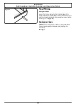
Removing the Control Panel
To remove the handrail, remove the two end bracket fixing
screws (
Fig. 9.3
). These may be hidden by removable covers.
Pull these to remove.
Now remove the 2 cross-headed screws hidden behind the
handrail end brackets (
Fig. 9.4
).
Pull off all the control knobs and remove the fixing screws
underneath the control panel (
Fig. 9.5
).
The control panel will drop down slightly. Clear the holes
from the inner panel and pull the control panel forward. Take
care not to damage or strain the wiring.
Fig. 9.1
Fig. 9.2
Fig. 9.3
Fig. 9.4
Fig. 9.5
9. Conversion to LP Gas


