background image

8

ArtNo.270-0003

Proplus control to low

ArtNo.270-0001

Proplus control to high

The Grill / Glide-out Grill  

(dependant on model)

n

n

CAUTION: This appliance is for cooking purposes 

only. It must not be used for other purposes, for 

example room heating.

n

n

CAUTION: Accessible parts may be hot when the grill 

is in use. Young children should be kept away.

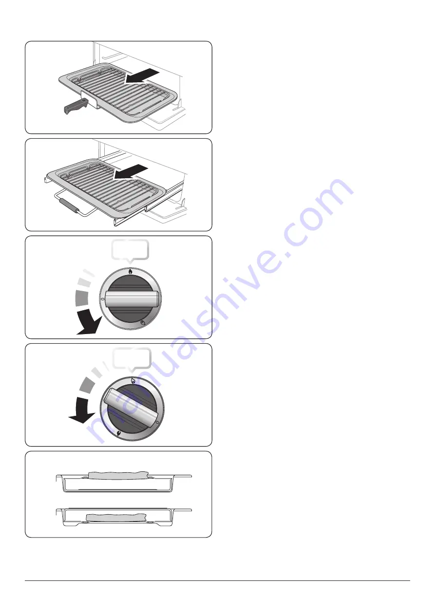
Open the door and, using the handle, pull the grill pan  

(Fig. 2.15) or carriage (Fig. 2.16) forward.
The burner does not glow red when in use; food cooks from 

the heat of the flame. The first time you light the grill there 

may be a little smoke given off – this is perfectly normal.
The grill has a special safety device which stops the flow of 

gas if the flame goes out.
To turn on the grill, press the igniter button and then press 

and hold the grill control knob to the large flame symbol (

for about 10 seconds (Fig. 2.17).
If, when you release the control knob the burner goes out, 

then the safety device has not held in. Turn the grill control 

knob to ‘0’ and wait for one minute. Repeat the operation but 

hold the button and control knob in for slightly longer.
The low position, marked with the small flame symbol, is 

beyond high, not between high and off (Fig. 2.18).
For best results, slide the grill pan back into the grill chamber 

and preheat the appropriate part(s) of the grill for two 

minutes. The grill trivet can be removed and the food placed 

on it while you are waiting for the grill to preheat.

n

n

DO NOT leave the grill on for more than a few 

moments without the grill pan underneath it, 

otherwise the knobs may become hot.

Once the grill has preheated, slide the grill pan out again. 

With the trivet back in place with the food on it, slide the pan 

back into the grill chamber. Make sure that it is pushed right 

in.
The grill pan trivet can be turned over to give two grilling 

positions (Fig. 2.19).

n

n

Never close the grill door when the grill is on.

ArtNo.331-0002 Grill pan high/low position

ArtNo.330-0003 - Grill pan w handle pulled forwards

ArtNo.331-0001Grill pan pulled forwards

Fig. 2.15 

Fig. 2.16 

Fig. 2.17 

Fig. 2.18 

Fig. 2.19 

Summary of Contents for Kitchener 100

Page 1: ...Kitchener Professional 100 Gas Built from experience USER GUIDE INSTALLATION INSTRUCTIONS U110756 01...

Page 2: ...ook Twitter message or Instagram comment 4 We cannot guarantee your kitchen will be professionally photographed 4 Any photographs received and professional photographs taken will belong to AGA Rangema...

Page 3: ...equirements and Regulations 26 Provision of Ventilation 26 Location of Cooker 27 Positioning the Cooker 28 Moving the Cooker 28 Lowering the Two Rear Rollers 29 Completing the Move 29 Fitting the Stab...

Page 4: ...ii...

Page 5: ...way from the cooker and never wear loose fitting or hanging clothes when using the appliance DO NOT use a steam cleaner on your cooker Always keep combustible materials e g curtains and flammable liqu...

Page 6: ...d If you use a combination of oils or fats in frying stir them together before heating or as the fats melt Foods for frying should be as dry as possible Frost on frozen foods or moisture on fresh food...

Page 7: ...unobstructed DO NOT use harsh abrasive cleaners or sharp metal scrapers to clean the oven door glass since they can scratch the surface which may result in shattering of the glass Make sure the shelve...

Page 8: ...before carrying out any thorough cleaning Allow the cooker to cool In the interests of hygiene and safety the cooker should be kept clean at all times as a build up in fats and other food stuff could...

Page 9: ...ow of gas if the flame goes out When the igniter button is pressed in sparks will be made at every burner this is normal Do not attempt to disassemble or clean around any burner while another burner i...

Page 10: ...are NOT recommended Fig 2 6 They will reduce burner performance and could damage the pan supports You should also avoid using unstable and misshapen pans that may tilt easily and pans with a very smal...

Page 11: ...is non stick and metal cooking utensils e g spatulas will damage the surface Use heat resistant plastic or wooden utensils n n Do not put it crossways it will not fit properly and will be unstable Fig...

Page 12: ...device has not held in Turn the grill control knob to 0 and wait for one minute Repeat the operation but hold the button and control knob in for slightly longer The low position marked with the small...

Page 13: ...shes cooked below approximately 10 C lower Fig 2 22 You can therefore cook dishes requiring different temperatures at the same time S Slow Cooking Left hand Oven The S setting Fig 2 23 is a very low t...

Page 14: ...tes hot air continuously which means faster more even cooking The recommended cooking temperatures for a fan oven are generally lower than a conventional oven Operating the Ovens Operating the Gas Ove...

Page 15: ...using the tall oven you can cook on all four shelves at the same time but make sure that they are well spaced out to allow the hot air to circulate The Handyrack Main Oven The Handyrack Fig 2 34 fits...

Page 16: ...apsed 1 Turn the Timer A knob to the Minute Minder E setting it should click into position Fig 3 2 2 Turn the Adjusting B knob to set the amount of time required Minimum time 1 minute Fig 3 3 3 Turn t...

Page 17: ...rrent time plus the additional cooking time you have set Fig 3 6 3 Turn the Timer A knob to the Auto H setting The display will show the current time the cooking symbol and the word AUTO Fig 3 7 4 Onc...

Page 18: ...ed it will emit an alarm and the Multifunction Oven will stop working The Cooking symbol on the display will disappear and the word AUTO will flash Fig 3 13 7 Once the specified time has elapsed it wi...

Page 19: ...n the clock display flashes 0 00 and AUTO During the time setting process the centre dot will flash When the process is complete the dot will stop flashing and the symbol will be displayed The time of...

Page 20: ...and then press the button or button until the required cook period shows Fig 4 10 Now press and hold the button Fig 4 11 and then press the button or button until the required stop time shows Fig 4 1...

Page 21: ...od until the display shows the Tone Bars Fig 4 14 Release the button and immediately press again this will adjust the tone down by a bar Continue the process until a comfortable tone is reached NOTE D...

Page 22: ...s Other containers should be placed centrally Keep all trays and containers away from the back of the oven as overbrowning of the food may occur For even browning the maximum recommended size of a bak...

Page 23: ...3 hours 80 90 minutes 15 25 minutes 10 15 minutes 20 30 minutes 30 40 minutes 20 30 minutes on a preheated tray 35 45 minutes 10 20 minutes according to size 20 40 minutes according to size 2 3 hours...

Page 24: ...hole in the base Check that the burner head is level and that the cap is fitted centrally on the burner head Fig 5 1 The Wok Burner The wok burner can also be taken apart for cleaning When reassemblin...

Page 25: ...a nylon brush The grill pan can be easily removed for cleaning as follows Remove the grill pan support frame by pulling the grill pan forward Fig 5 3 Lift the grill pan clear of the support frame The...

Page 26: ...cleaner Table 5 1 Take care not to disturb the oven thermostat temperature sensor at the top of the oven opening Fig 5 9 The enamelled oven burner trim Fig 5 10 can be removed for cleaning The oven b...

Page 27: ...steel Warm soapy water Do not use abrasive cleaners on lettering Control knobs handles trims Plastic chrome copper or lacquered brass Warm soapy water soft cloth Brass Brass polish Oven door glass gl...

Page 28: ...lectrical supply remember to reset the clock to make sure that the timed oven continues to operate Food is cooking too slowly too quickly or burning Cooking times may differ from your previous oven Ch...

Page 29: ...of the hinge to set the hinge position Fig 6 4 Retighten the hinge screws NOTE The tall oven door cannot be adjusted Grill The fascia gets hot when I use the oven or grill The cooker is cooled by a f...

Page 30: ...lling or BS5482 3 when the installation is in a boat The Gas Safety Installation and Use regulations The relevant Building IET regulations In the Republic of Ireland the cooker must be installed in ac...

Page 31: ...use on LPG must not be installed in a room or internal space below ground level e g in a basement You will need the following equipment to complete the cooker installation satisfactorily Stability bra...

Page 32: ...es and rear of the appliance should be heat splash and steam resistant Certain types of vinyl or laminate kitchen furniture are particularly prone to heat damage and discolouration We cannot accept re...

Page 33: ...hain should be kept as short as is practicable and fixed firmly to the rear of the cooker If you are using a stability bracket first attach the bracket location device to the rear of the cooker Fig 7...

Page 34: ...dards Hoses may be purchased at most builders merchants The gas supply needs to terminate with a down facing bayonet Fig 7 12 The connector is located just below the hotplate level at the rear of the...

Page 35: ...The cooker is supplied with a 3 core cable 2m long If a replacement cable is fitted it must be 250V high temperature PVC 85 C 1mm Should the plug not fit the socket in your home it should be removed...

Page 36: ...fixings Remove the 4mm Allen screws from the top corners of the fascia Fig 7 16 Fit the front handrail in position and secure using the 4 mm screws Fitting the 1 piece Plinth Professional Loosen the t...

Page 37: ...ection hose suitability etc When servicing or replacing gas carrying components disconnect from gas before commencing operation and check appliance is gas sound after completion Do not use re conditio...

Page 38: ...or strain the wiring Oven Thermostat Bypass Remove the thermostat bypass screw and fit the new one in each oven see the back page of this book for the correct bypass screws Refit the control panel Gr...

Page 39: ...umber 1 Q030836 Conversion Kit Contents Table 8 1 below describes the contents of the Universal Conversion Kit Large Injector LPG 87 x 2 Medium Injector LPG 68 x 2 Small Injector LPG 51 x 1 Wok Inject...

Page 40: ...ator Harness 5 lead H7 HT Lead Grill H8 Wire Assembly Cooling Fan live link W1 NI Wire Assembly Earth Link NI Wire Assembly Earth x2 NI Earth Harness Assembly Part No P064515 P064454 Fanned Oven Harne...

Page 41: ...5kW 255 g h internal 53 external 126 external 82 Rapide Large Burner 40 3 kW 134 3 0 kW 218 g h 87 Semi Rapide Medium Burner 32 1 7kW 109 1 7 kW 124 g h 68 Auxiliary Small Burner 28 1kW 75 1 0 kW 73 g...

Page 42: ...h internal 53 external 126 external 82 Rapide Large Burner 40 3 kW 134 3 0 kW 218 g h 87 Semi Rapide Medium Burner 32 1 7kW 109 1 7 kW 124 g h 68 Auxiliary Small Burner 28 1kW 75 1 0 kW 73 g h 51 Gril...

Page 43: ...as burners 5 Auxiliary Small Burner EE gas burner Semi Rapide Medium Burner EE gas burner 58 Semi Rapide Medium Burner EE gas burner 58 Rapide Large Burner EE gas burner 56 Rapide Large Burner EE gas...

Page 44: ...hand Efficiency Fuel type Electric Cavity type Fanned Power conventional kW Power forced air convection kW 2 5 Volume Litres 82 Energy consumption electricity conventional kWh cycle Energy consumptio...

Page 45: ...41 Notes...

Page 46: ...42 Notes...

Page 47: ...organisations other than those authorised to act on behalf of AGA Rangemaster Exceptions Items not included under the free 1 year guarantee include pan supports griddles wok rings baking trays grill p...

Page 48: ...CV31 2AD England Consumer Services 44 0 800 804 6261 or 0 370 789 5107 from a mobile Fax 44 0 1926 450526 E mail consumers agarangemaster co uk www rangemaster co uk For UK Trade Enquiries Tel 44 0 11...

Reviews: