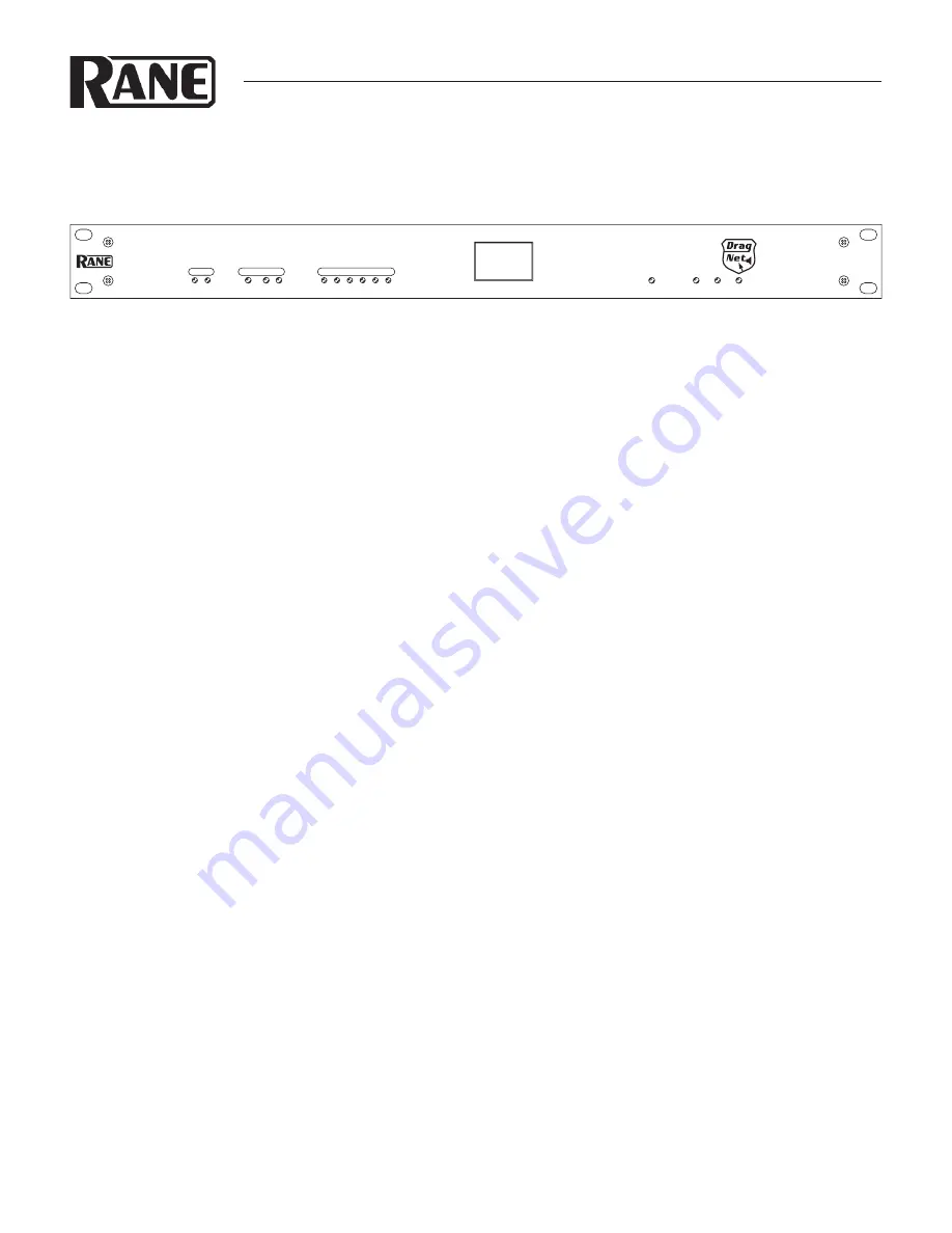
Manual-1
RPM 26z
PROGRAMMABLE MULTIPROCESSOR
HARDWARE MANUAL
WEAR PARTS:
This product contains no wear parts.
QUICK START
This section is intended to help you make the physical connec-
tions and software manipulations necessary to get up and run-
ning with your sleek new RPM 26z. If you don’t read the entire
Hardware Manual, at least read this section. It is also recom-
mended that you read the Quick Start section of the Drag Net
Software Manual. If the Drag Net software is not yet installed
on your computer, please install it now.
To be safe, leave the audio connections until last. Begin by
connecting the IEC power cord. Observe that the
POWER
LED
on the front panel illuminates. After a few seconds, the
STATUS
LED should turn from red to yellow to green, and the
PRESET
display should have a number in it (00, if it’s the first time you’ve
powered the device). If the
POWER
comes on, but the
STATUS
LED does not turn green, contact the factory.
Connect one end of the Ethernet crossover cable (supplied
with the unit) to the
10Base-T
jack on the rear panel. Connect
the other end of the cable to an Ethernet port on your computer.
The
LINK
LED on the rear panel should be lit. If it is not,
verify that you are indeed using a crossover cable, not a standard
Ethernet cable. A standard Ethernet cable should only be used
if you are connecting the RPM 26z and a computer indirectly
using an Ethernet switch. Launch the
Drag Net
application
and follow the steps to create a new project and new RPM
26z device configuration. Click the
Configure Hardware IP
shortcut and follow the instructions to set the unit’s IP address
to be compatible with your computer’s Network settings.
Tip: If
you aren't sure what IP to use, try the address 192.168.69.69 and
subnet 255.255.255.0. This finds the default factory address without
manually setting it.
INPUT
AES3
OUTPUT
1
2
A
B
1
4
3
2
6
5
LOCK
VIP
POWER
ETHERNET STATUS
RPM 26z
PROGRAMMABLE
MULTIPROCESSOR
PRESET
24
Now click on the
Poll
button in the toolbar. A device name
and IP address should appear under the
Live
folder in the
Project
window. If a device does not appear, consult Drag Net’s
online
Help
for instructions on configuring and verifying your
computer’s Network settings.
The audio path within the RPM 26z is displayed in Drag
Net’s
Device Configuration
window as a collection of blocks
wired together to form a
Processing Map
. These maps are cre-
ated offline as
Storage
configurations, which are then trans-
ferred to a
Live
unit. Drag blocks from the
Palette
onto the
Processing Map
and wire them together to create the audio
path. Save this file frequently using the
File > Save command
.
Transfer the selected
Storage
configuration to a
Live
unit using
the
Transfer Config
button in the
Project
window. A new,
minty green
Device Configuration
window opens once the
transfer is complete, indicating you are now online with a
Live
device. Double-click a processing block to display and adjust its
Properties
(parameters) in real time on a
Live
device — there
is no need to go offline to make parameter changes.
Once you have a useful configuration in the unit, connect
balanced audio
INPUTS
and
OUTPUTS
to the Euroblocks on
the rear panel, then turn on the amplifier. As a precautionary
measure, all outputs are muted during
and
after a configuration
transfer. Unmute each output individually, or use the handy
Mute Outputs
button in the toolbar. Once all outputs are
unmuted, audio passes through the unit along the connections
you
defined.


