Rane RPM 26i Operator'S Manual Download Page 17

Manual-17

volume down for a given increase above the 

Threshold

. The

Attack

 time dictates how quickly the signal reaches a

“settled” compression level for a given input signal step size.
The 

Release

 time dictates how long it takes the output signal

to reach a “settled” level after the input signal is reduced.

The 

Comp.

 indicator lights yellow when the compressor

threshold has been reached. All other Compressor settings are
adjusted in the Compressor detail window shown at the
bottom of this page.

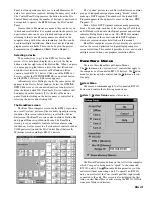
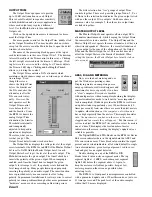
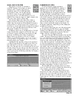
Double-clicking on the Compressor block opens the detail

window. The name of the open Compressor appears at the top
of the window. The detail window contains a scroll bar for
adjusting the 

Threshold

Ratio

Attack

 time and 

Release

time. A gain reduction meter is also provided that indicates
the amount of gain reduction (attenuation) in dB. The

Compressing

 indicator at the bottom left corresponds to the

top Gain reduction indicator and to the yellow indicator
shown on the Compressor block on the Device Edit screen.

The Compressor uses an RMS detector for Threshold

detection. Avoid short Attack and Release times as they can
audibly distort the signal, especially when the signal contains
mostly low frequencies.
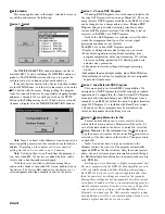
The 

Combine

 check box allows logical “or-ing” of the

compression settings. 

Only if both channels’ 

Combine

 boxes

are checked will the “or-ed” settings apply to both channels.

When both boxes are checked, and after either channel
reaches its 

Threshold

 setting, both compressors will “follow”

each other with the same gain reduction, 

Attack

 and 

Release

times being applied to both channels. The channel with the
most gain reduction 

always

 dictates what instantaneous gain

reduction, attack and release settings are applied to the
combined channels. This maintains the spectral balance
between the two channels and keeps your stereo program’s
left-to-right sound stage intact.

If only one channel’s 

Combine

 box is checked, that

compressor uses the higher gain reduction value of the two
compressors as well as that same compressor’s 

Attack

 and

Release

 times. The unchecked channel acts by itself.

The Compressor’s 

Threshold

 and 

Ratio

 settings can also

be edited if you click and drag directly on the graphed curve
itself. You must click directly on the curve, to the left of the
Threshold point (or knee), to alter the 

Threshold

. The vertical

position of the cursor corresponds to the 

Threshold 

level once

the curve is successfully grabbed. Click directly on the curve
to the right of the knee to alter the 

Ratio

 setting. The curve

changes color when successfully grabbed.
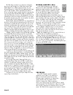
DELAY

All DSP Programs provide two types of Delay blocks.

Coarse Delay in the Input Block section, before the cross-
overs or splitters, and Fine Delay in the Output Block, after
the crossovers or splitters.
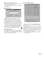
COARSE DELAY

The Coarse Delay block provides 1 millisecond minimum

step sizes. Coarse Delay is useful in speaker stack applica-
tions where stacks are placed many feet in front of the stage
or for distributed speakers that are far from the sound source.
One millisecond is approximately 1.13 feet or 0.34 meters.

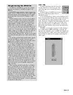
The up or down arrows in the Coarse Delay block (shown

at above right) increment or decrement the Coarse Delay
without opening the detail window.

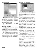
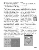
For direct or scroll bar editing, open the detail window by

double-clicking on the Coarse Delay block. This opens the
Coarse Delay detail window where a scroll bar provides three
easy ways to edit the delay value. Click the left
or right arrows to adjust the delay one millisec-
ond at a time. Click between the arrows and
the sliding box (Thumb) to adjust the delay in
10 millisecond steps. Click and hold directly
on the Thumb to drag the control. Click
directly in the edit box to display the cursor
and type in the desired value.

Note:

 The Coarse Delay’s minimum setting is one milli-

second. Values less than 1 millisecond are not valid, since the
minimum time it takes signal to propagate through the
RPM 26i is 2.4 ms. The propagation delay of the RPM 26i is
included in the setting. So, what you see is what you get.

Subnote: The propogation delay varies with the input

sample rate. A 48 kHz input produces 2.4 ms propogation,
and 96 kHz produces 2.0 ms.

The 

Global Settings

 for 

Delay Units

 (milliseconds, feet

and meters) and 

Temperature

 are covered next, under FINE

DELAY.

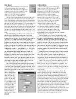
The Coarse Delays can be locked together by checking the

Linked

 box. A red ‘

1

’ appears in the Coarse Delay block on

the Device Edit screen when the 

Linked

 box is checked. This

indicates that the control is linked without the need to open
the detail window. The delays are not linked together unless
at least one pair of 

Linked

 boxes are checked.

Summary of Contents for RPM 26i

Page 1: ...AUTION Do not connect anything but an approved Rane power supply to this jack The unit does ground the chassis through the power cord If the RS 3 and the RPM 26i are getting power the yellow front panel POWER indicator will be on Start your computer run Windows and launch RaneWare by double clicking on the RaneWare umbrella icon See the next page for software installation instructions The Help fil...

Page 2: ...shers that the cable screws into Be sure to screw down RS 232 cables to guarantee good shield connections The chassis and the audio signal ground are connected together internally at only one point The RPM 26i chassis connects through the RS 3 power supply cables to the earth ground 3rd pin of the 100 and 120 VAC line cords A 6 32 screw and star washer are also provided on the unit s rear if a tec...

Page 3: ...n the appropriate DSP Programs for your system This avoids the problem of accidentally recalling a Memory which could be detrimental to the system On the other hand this feature is useful in rental systems for example where fixed DSP Programs can be stored in various Memo ries requiring only an MRP wiring alteration to change the signal processing from a 2 way to a 3 way system 햶 RW 232 OUTPUT con...

Page 4: ...r crashes the unit continues to operate and keeps its current settings If the unit loses power all current settings are saved and automatically recalled upon power up unless an MRP contact switch is on then it recalls the selected MRP Memory See Memory Recall Port on page Manual 23 The Windows screens perform the traditional function of a front panel displaying and editing the device s settings Fo...

Page 5: ...wn below is called the Device Edit screen The RaneWare screen also contains a Button Bar and typical Windows pull down Menus The RaneWare screen gives you complete control of all signal processing functions as well as access to all system level controls such as COM port selection and the Site Control Panel that recalls Memories stored in multiple RW 232 devices The system picture in each Device Ed...

Page 6: ...ond for the RW 232 unit Check the Show Memory Names check box to display the Memory names in the RaneWare Button Bar whenever the mouse is on top of a Memory recall button Memory names are edited in the Site Control Panel Setup window See Site Control Panel Setup below The Remote to RPD 1 check box is only used with Rane s RPD 1 product Check this box only if you are using an RPD 1 to remotely com...

Page 7: ... Note The names you assign become the Memory names associated with each RW 232 device on line regardless of the type of device RPM 26i RPE 228 ECS Teleconferencing system etc If you set up the button corresponding to Memory number 1 to represent a particular sound system configuration make sure Memory number 1 in each device in the system is pre programmed appropriately for this particular sound s...

Page 8: ...s return or click OK Note You do not have to type an extension to the filename unless you want to The program automatically appends RPM as the file extension Also the current project name site and system engineer information entered through the Edit Installation Info dialog box is automatically saved in each RPM file Backing up device Memories is highly recommended Just like any computer data the ...

Page 9: ...ice Lock Device Lock Device allows you to lock a device to prevent unauthorized users from making changes to your pro grammed settings in the device s Memories Although a device is locked different presets can still be recalled by selecting another Memory via the Site Control Panel the Memory Recall Port or by clicking on a desired Memory key on the button bar with the mouse The data previously st...

Page 10: ...ve window appears You can select one or more Memories to print To select a single Memory to print click on your choice then click OK As with many Windows selection boxes to select a contigu ous range of Memories click on the first Memory choice then hold down the Shift key and click on the last Memory choice of the range This is a handy way to print Memories 1 through 5 for example or even all 16 ...

Page 11: ...to Filter 1 s new values Filter 2 s settings do the same et cetera Ramping is disabled via the Ramp Disable checkbox at the bottom of the Device Edit screen It is wise to keep like numbered filters in a similar frequency range when changing Memories For example always set filter number one as your lowest frequency PEQ filter This way when changing Memories where filters move the ramping algorithm ...

Page 12: ...d DSP Program the Inputs and Crossovers check boxes near the top of the screen allow the user to reduce the DSP Program list to include only those Programs matching the checked criteria For example if one desires only two input 3 way crossovers de select all but the Two Input and 3 Way check boxes The displayed list is then reduced to only two DSP Programs both Programs 4 and 5 provide a Dual 3 wa...

Page 13: ...ng entire Input or Output block settings If you find yourself squeezed for room at the bottom of the screen you can modify the Task Bar so it only appears when you move the mouse pointer below the bottom of the screen To do this Right Click on a blank spot on the task bar Select Properties Enable Auto Hide Click OK While operating the Site Control Panel in Windows there is no button box for the sy...

Page 14: ...our pal the Windows operating system Displaying meters on computers poses a unique problem for software designers and sometimes for users especially if you have a slow computer Everyone is familiar with analog meters without computers deciding that display ing meter indicators needs to wait until a more important task is completed Windows provides the RPM 26i software an update window opportunity ...

Page 15: ... select a different filter s settings You may also click directly on the circled number on the graph corresponding to the filter to edit or view it The Freq Hz edit box is changed with the up or down arrows Or click in the edit box to display the cursor and type a new frequency value always in integer Hertz The Level dB edit box is also changed with its up or down arrows Or click in the edit box t...

Page 16: ...in three ways Clicking the left or right arrows adjusts the bandwidth one step at a time Clicking between the arrows and the sliding box thumb adjusts the bandwidth 10 steps at a time Clicking and holding the thumb allows dragging the control A Bypass check box appears on the bottom right allowing the selected PEQ filter to be bypassed This is essentially equivalent to setting that filter s level ...

Page 17: ...f You must click directly on the curve to the left of the Threshold point or knee to alter the Threshold The vertical position of the cursor corresponds to the Threshold level once the curve is successfully grabbed Click directly on the curve to the right of the knee to alter the Ratio setting The curve changes color when successfully grabbed DELAY All DSP Programs provide two types of Delay block...

Page 18: ...ous DSP Programs in the RPM Up to a mono 6 way crossover can be implemented with the RPM 26i s powerful Extended Parametric EQ see the Extended Parametric PEQ section on pages Manual 15 16 for details on implementing more than a 3 way crossover The 2 and 3 way crossover interfaces are similar Only the 3 way is covered here The 2 way interface simply removes one band The 3 way crossover block is sh...

Page 19: ...onnected to amplifiers and speakers This avoids the potential catastrophe of slipping with the mouse or reaching again for your latté and accidentally clicking the mouse SUMMING AND I O ROUTING Some DSP Programs provide simple Input Summing that is generally accompanied by I O Routing The circled plus sign between the two Input Blocks indicates that summing is supported A schematic drawing of a th...

Page 20: ... RPM 26i The graph in the example above does not show the contribution of the crossover since the Crossover box is unchecked Right mouse click on the Detailed Response Window to zoom in or out or to print LIMITER For most DSP Programs each output is supplied with a Limiter The limiter is meant to be a safety device to stop the RPM 26i Output from exceeding a predetermined threshold voltage The Lim...

Page 21: ... hearing specific frequency room reflections The signal Generators default to a Muted state when new DSP Programs containing Generators are requested Click Mute to unmute the Generator Click the up or down arrows to adjust the Generator s Level in dB steps The maximum attenuation is 40 dB The Generator levels are calibrated in dBFS i e at 0dB the Generator is sending a full scale digital signal to...

Page 22: ...er up the unit may need erasing This reinitializes all of the stored parameters including names and resets all Memories to DSP Program 3 To erase hold the DEFAULT button while turning the power on Be sure to hold the DEFAULT button until the Output LEDs cycle When the unit is finished erasing the Output LEDs cycle yellow from the outsides to the center If you are unable to stop either the Output 1...

Page 23: ...nges in contact position s are detected either latching or momentary switches may be used However when wiring contacts only use Normal Paging or Binary mode do not switch between modes The MRP may be programmed so that any input code including no connection may recall any Memory 1 2 3 4 5 6 7 8 Mode Result 1 0 0 0 0 0 0 0 1 0 1 0 0 0 0 0 0 2 0 0 1 0 0 0 0 0 3 0 0 0 1 0 0 0 0 4 0 0 0 0 1 0 0 0 5 0 ...

Page 24: ...102 01100110 103 01100111 104 01101000 105 01101001 106 01101010 107 01101011 108 01101100 109 01101101 110 01101110 111 01101111 112 01110000 113 01110001 114 01110010 115 01110011 116 01110100 117 01110101 118 01110110 119 01110111 120 01111000 121 01111001 122 01111010 123 01111011 124 01111100 125 01111101 126 01111110 127 01111111 128 10000000 129 10000001 130 10000010 131 10000011 132 100001...

Reviews: