
Manual-
Audio Connections
As a safety precaution, turn all devices (especially power amplifi-
ers) OFF when making connections. Doing so gives you a chance
to find and correct wiring mistakes and prevent damage to your
amplifiers, speakers, ears, pets, etc.
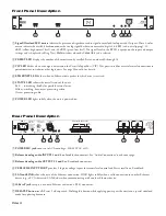
Analog Inputs and Outputs
The RPM 2 has two balanced analog Inputs and two bal-
anced analog Outputs.
For each Input or Output Euroblock connector:
• Connect the (positive) audio line to the ‘+’ terminal.
• Connect the (negative) audio line to the ‘–’ terminal.
• Connect the cable shield to the shield terminal.
For those installations where the RPM 2’s internal shield-
to-chassis connection causes interference, connect each shield
directly to the chassis PEM nut located above each Euroblock
connector, keeping the shield wrapped around the audio conduc-
tors as much as possible.
For optimum Electromagnetic Interference (EMI) immunity,
connect the shields at both ends of the cable. See the RaneNote
“Sound System Interconnection” for more information on system
connections and proper grounding practices.
Analog Input Stage
Each analog input uses a fixed analog gain approach. A Digital
Trim control is located immediately after the A/D converter. The
RPM 2 takes the following approach to input clipping:
The analog input stage accepts a full level of +24 dBu. It
is not possible to clip the A/D converter with normal audio
sources, since there is no additional gain between the initial
input stage and the A/D converter. The Digital Trim control,
located after the A/D converter, can be set to clip the signal to
your heart’s content, so adjusting this trim to provide the hottest
signal to the DSPs
without
clipping is the most important step
when setting up gain structure. For this reason, a dedicated
meter displaying the signal level being passed to the DSPs is
provided in each Analog Input block.
If the DSPs are working with a clipped signal, the audio is (as
expected) distorted and none too pretty, but it is not a drastic,
damaging sound. And while it’s technically possible to write a
DSP algorithm to emulate the glorious clipping distortion of
vacuum tubes, it’s not particularly useful for an installed sound
system, where the DSP power could be put to better use remov-
ing that annoying 500 Hz feedback from the podium mic. Plus,
they don’t yet make DSP chips with gold-plated substrates for
those celestial highs and that moist, supple midrange.
Analog Output Stage
Each analog output uses a similar approach. There is a Digital
Trim control located immediately
before
the D/A converter. It’s
as simple as that.
Control Connections
Versatile Input Port (VIP)
Eight logic input pins are provided, each capable of accepting
DC voltage between 0-5 VDC. VIP pins are used with contact
closure switches for Preset recall, or with potentiometers for
remote Level control. The functionality (Preset recall versus
control) of each pin is assignable as part of the Device Configu-
ration.
• The maximum allowable voltage on any VIP pin is 5.3 VDC.
• Use of twisted pair cable is recommended for lower noise.
• If an external device is used to generate a 0 to 5 volt signal,
connect the ground of the external device to the VIP GND.
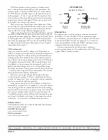
Preset Recall Using Contact Closure Switches
The minimum “low” voltage required to detect a contact closure
and change Presets is 2.5 V. Since the internal pull up is 100 kΩ
to +5 V, it is possible to calculate the maximum allowable cable
length, provided the wire resistance per foot (or meter) is known.
Example
:
To be safe, let’s allow a maximum of 80 kΩ worth of cable
resistance. This value keeps the voltage divider formed by the
100 kΩ internal resistance and 80 kΩ cable resistance from
dropping below 2.5 V.
(5 V * 100 kΩ) / (100 kΩ + 80 kΩ) = 2.777 V
If the cable resistance is 30 Ω per 1,000 feet (305 meters)
(1,000 ft / 30 Ω) * 80,000 Ω = 2,666,666 ft (813 km)
Thus, you can only use 2,666,666 feet (505 miles) of twisted
pair cable before the Preset recall functionality becomes inter-
mittent (assuming the cable is properly twisted and not run
through excessive magnetic or electric fields).
Remote Level Control Using Potentiometers
The VIP inherently prefers linear taper 10 kΩ potentiometers,
which provide a nice audio taper “feel” for the end user. When
used with suitable twisted pair wiring, the 10 kΩ value also of-
fers acceptable noise immunity and long cable lengths.
AMX and Crestron Control
There are two ways to control a Drag Net device from an AMX
or Crestron system. Use either Ethernet connectivity or use the
rear panel Versatile Input Port (VIP). Each of the 8 VIP pins
supports either switch closure Preset recall or zero-to-five volt
control of Level.
Many AMX/Crestron applications require simple Level con-
trol and/or Preset recall. This is most easily accomplished using
the VIP (Versatile Input Port) found on all Drag Net devices.
There are always more Drag Net products coming — both hard-
ware and software, so check our home page for the most recent.
VIP Preset Recall
Connect a switch closure or relay to a VIP pin and short it to
the ground (GND) pin to recall the corresponding Preset. For
example, shorting VIP pin 1 to the GND terminal recalls Preset
1; pin 2 recalls Preset 2, etc. There are more details about this
functionality in the Drag Net Help file and on our Drag Net Ap-
plications page. Be certain to appropriately set the VIP Alloca-
tion in Drag Net's Parameter Window.


