Manual-3
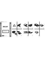
Rear Panel Description
1
XLR INPUT jacks:
These accommodates balanced signals. Rane adheres to the international and U.S. standard for balanced pin
configurations: Pin 1 is chassis ground (neutral), pin 2 is hot (positive), and pin 3 is signal return (negative)
.
Choose between this
and the ¼" TRS Input jack—use only one—they do not sum.
2
¼" TRS INPUT jacks:
These TRS (tip-ring-sleeve) ¼" jacks accommodate either balanced or unbalanced signals. Balanced
signals use microphone cable (two conductor with shield) with TRS ¼" plugs. Unbalanced signals use a mono ¼" TS plug (single
conductor with shield), with its length kept under 10 feet (3 meters) to avoid hum and noise.
Choose between this and the XLR Input
jack—use only one—they do not sum.
Refer to the included RaneNote, “Sound System Interconnection” for unbalanced wiring.
3
¼" TRS OUTPUT jacks:
These are TRS (tip-ring-sleeve) ¼" balanced jacks compatible with either balanced or unbalanced
systems. For balanced systems, use a microphone cable wired with pin 1 is chassis ground (neutral), pin 2 is hot (positive), and pin
3 is signal return (negative)
.
Refer to the RaneNote, “Sound System Interconnection” for unbalanced wiring.
4
XLR OUTPUT jacks:
These balanced outputs are wired per AES standards of pin 2 “hot”, as described above in
1
.
5
Universal Voltage Input:
via a miniature IEC 60320 C6 appliance inlet. This mates with an IEC 60320 C5 line cord (USA
domestic). Do
not
lift the ground connection!
ME15S Connection
INPUTS
Both XLR and ¼" TRS Inputs are wired in parallel and are
actively balanced. Each works equally well. Choose strictly from
a required hardware point-of-view, there will be no performance
trade-offs. The wiring convention adheres to American, British
and International standards of pin 2 or tip being hot, pin 3 or
ring being return, and pin 1 or sleeve being shield. Unbalanced
operation involves using only pin 2 or tip as signal, and pin 1 or
sleeve as shield or ground. It is not necessary to short any inputs
to ground—it doesn’t hurt, it’s just not necessary. Use pin 1, or
the shell, for shield ground.
WIRING
TIP / PIN 2 = POSITIVE
RING / PIN 3 = NEGATIVE
SLEEVE = SIGNAL GROUND
PIN 1 = CHASSIS GROUND
ALL AUDIO IS CLASS 2 WIRING
CHANNEL 1
OUTPUT
INPUT
CHANNEL 2
OUTPUT
INPUT
MADE IN U.S.A.
RANE CORP.
ME15S
ACN 001 345 482
COMMERCIAL AUDIO
EQUIPMENT 24TJ
R
100-240 V
50/60 Hz 7 WATTS
This device complies with Part 15 of
the FCC Rules. Operation is subject
to the following two conditions:
(1) this device may not cause
harmful interference, and (2) this
device must accept any interference
received, including interference that
may cause undesired operation.
4
5
3
1
2
4
3
1
2
OUTPUTS
The Outputs mimic the Inputs. Balanced output requires using
pin 2 or tip, and pin 3 or ring for the signal. It does not require
pin 1 or shield. The signal exists differentially between the two
balanced leads; ground is not involved. For hum-free systems
ground is used only for shielding.
EXPANDING
Expanding and/or daisychaining the Inputs and Outputs nor-
mally uses the ¼" jacks. Three parallel Input connectors allows
driving a second signal processor or amplifier without special
cabling.
SIGNAL LEVELS
Signal levels from -10 dBV to +4 dBu are considered normal
and within range (at least 20 dB of headroom exists above these
levels). Do not directly connect microphones into the ME15S.
These require a mic preamp.