Manual-2
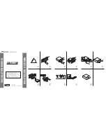
FRONT PANEL DESCRIPTION
햲
POWER LED
illuminates whenever the appropriate power supply is connected to the unit with the correct line voltage
source.
햳
Channel BYPASS switches and LEDs:
When the BYPASS switch is in the
in
position the red BYPASS LED illuminates
and the channel is in the BYPASS mode. In this mode the audio signal is routed directly from the INPUT to the OUTPUT
jacks without passing through any active circuitry (often referred to as hard-wire bypass). Use this switch to compare
equalized and unequalized material. In the event of power failure, the GE 215 automatically goes into BYPASS.
햴
Channel OVERLOAD indicators
illuminate if any section of the same Channel of the GE 215 is within 3 dB of clipping.
Occasional blinking of this LED is acceptable, but if it remains on more than intermittently, turn down either the Channel’s
LEVEL control or reduce the output level of the preceding component to avoid distortion.
햵
Channel LEVEL controls
set the Level of the signal coming into the GE 215. Turn this control down if the OVERLOAD
LED lights up in it’a Channel steadily (meaning too strong an Input signal). Since actual unity gain depends on varying
slider settings (which is why we have not marked a unity gain position on the front panel), use the BYPASS switch to
determine the exact unity gain position of this LEVEL control by comparing EQ and BYPASS loudness.
햶
Filter Level slide controls
set output levels of each of the 30 bandpass filters for each Channel.