Rane CP 62 Operator'S Manual Download Page 6

Manual-6

CP R2 Source & Level Remote
Control

Table 1 shows the flexibility of configuring the R2. The

R2 controls operate the same as the PROGRAM SELECT and
ZONE LEVEL controls on the front of the CP 62, when
enabled by the front panel REMOTE CONTROL button.
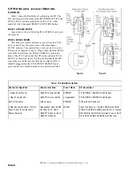
ZONE 1 STEREO MODE

Locate and set the switch in the R2 to STEREO, as shown

in Figure 1a.

ZONE 1 MONO MODE

This delivers a total of three mono zones from the CP 62.

Zone 1a and 1b use the same source with independent
LEVEL controls. To separate Zone 1 into 1a and 1b, use two
R2 remotes connected to Zone 1. Plug a cable from the MAIN
jack of the first R2 into the ZONE 1 REMOTE jack on the
back of the CP 62 and set the first R2s slide switch to DUAL
MONO, as shown in Figure 1b. Plug a cable from the MAIN
jack of the second R2 into the AUX jack on the first R2. A
third R2 plugged into the CP 62 ZONE 2 REMOTE jack
gives control over the third mono zone, operated as Zone 2.

Figure 1a.

Figure 1b.

Table 1. R2 Installation Options

Desired Configuration

Remote Functions

Zone 1 Mode

R2 Connections

1 Stereo Zone (Zone 1)

SELECT & stereo LEVEL

STEREO

CP 62 ZONE 1 SOURCE & LEVEL jack

1 Mono Zone (Zone 2)

SELECT & mono LEVEL

not applicable

CP 62 ZONE 2 SOURCE & LEVEL jack

Both of the above

both as above

STEREO

2 R2 units both as above

3 Mono Zones (Zones 1a, 1b, & 2)

Zone 1a and 1b use the same

Source Selection

Independent mono LEVEL

for Zone 1a, 1b, and 2.

SELECT for Zone 1a & 1b.

SELECT for Zone 2.

MONO

Use 3 R2s. Zone 1a - first R2’s MAIN to the CP 62

ZONE 1 SOURCE & LEVEL jack. Zone 1b - second

R2’s MAIN to the first R2’s AUX jack. Zone 2 - third

R2 to CP 62 ZONE 2 SOURCE & LEVEL jack.

DECORA is a registered trademark of Leviton Manufacturing Co., Inc.

Summary of Contents for CP 62

Page 1: ...of the CP 62 and its line cord into the AC line the PWR LED should come on Turn both ZONE LEVEL controls fully counter clockwise Turn the PROGRAM INPUT LEVEL LINE 1 up to 12 o clock Now it s OK to tu...

Page 2: ...ERNAL JUMPER OPTION described on page Manual 4 6 Front panel ZONE ASSIGN switch Selects which zone the rear panel selected paging input will be routed to and activate program ducking For more informat...

Page 3: ...INSERT jacks These unbalanced Tip Send Ring Return connectors allow insertion of external signal processors such as equalizers or compressor limiters Zone 1 is stereo or dual mono If zone 1 is used a...

Page 4: ...set by daisy chaining two optional R2 remote controls This overrides the front panel level control SOURCE LEVEL REMOTE INPUTS Two 4 pin modular jacks on the rear control source and level remotely usin...

Page 5: ...ich signal is controlled from the front panel PAGING ZONE ASSIGN switch and which is controlled via the rear panel REMOTE ZONE ASSIGN connector Rear Panel balloon 15 is determined by the rear panel PA...

Page 6: ...cable from the MAIN jack of the second R2 into the AUX jack on the first R2 A third R2 plugged into the CP 62 ZONE 2 REMOTE jack gives control over the third mono zone operated as Zone 2 Figure 1a Fi...

Page 7: ...y The ampere rating for tinsel wire is too low affecting system remote reliability Maximum cable distance from the CP 62 is 200 feet 2 Install a modular handset connector on each end of the telephone...

Page 8: ...ed Here are some things to try 1 Try combinations of lifting grounds on units that are supplied with ground lift switches or links 2 Verify that all chassis are tied to a good earth ground i e through...

Reviews: