background image

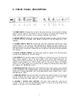
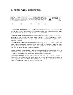
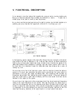
V. FUNCTIONAL DESCRIPTION

So, you have read the previous page and you’re ready to continue. Use the block diagram as a

pictorial guide as we describe the signal path of the AD 13. It will help you a lot.

If you attempt to read this without first digesting the previous section covering digital audio

theory you should be ashamed. Page numbers are included for a reason . . . . it gives one a

certain sense of the order in which to read this manual.

AD 13 BLOCK DIAGRAM

7

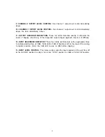
The next stop in the signal path is the pre-emphasis block This circuit boosts high frequencies

relative to the tower frequencies for two reasons: First, high frequencies are usually lower in
level than low frequencies and can be processed with higher resolution when boosted and
second, to reduce the output sensitivity of the unit when de-emphasis is applied at the output

to compensate for the pre-emphasis and return the overall frequency response to flat. The

lower high frequency sensitivity at the output results in a lower output noise level.

The next stop on the tour is the input level control. From the input level control the signal is

passed to the input gain adjustment amplifier which preconditions the audio signal for
presentation to the nine pole elliptic anti-aliasing filter. The anti-aliasing filter prevents any

frequencies above 20kHz from entering the audio to digital converter. If they were allowed to

pass they would cause a great deal of difficulty with the meter reader and some severe
distortion at the output of the system.

In the beginning, signal is applied at the input either through the 3-pin connector or the barrier
strip. Whether the input is balanced or not, it will first pass through the Radio Interference

Filter to strip it of local police matters and reruns of Falcon Crest. It will then be applied to the

differential amplifier which unbalances a balanced input and rejects common mode noise on
the input lines. For unbalanced inputs the differential input amp behaves like a piece of
ordinary zip cord.

Summary of Contents for AD 13

Page 1: ......

Page 2: ......

Page 3: ...he Rane factory before taking it anywhere for repairs We will help you to identify and locate any specific malfunctions possibly avoid needless shipment or instruct you as to the speediest method for...

Page 4: ...his display is to inform the user as to the amount of delay currently applied to any of the three outputs these outputs being selected by the channel select switch and pointed to by the LED channel po...

Page 5: ...any of the respective output stages approach this sort of difficulty 12 lNPUT HEADROOM INDICATOR These four LEDs will illuminate at the appropriate times to indicate whetherthere is 20dB 12dB 6dB or...

Page 6: ...IN to their locked position places the respective output stage into its transformer balanced mode Pressing the switch again to release it from its IN position causes the output to be placed back into...

Page 7: ...a of the original signal All seriousness aside it really is almost that simple If you ve ever seen an audio waveform play in real time on an oscilloscope you have probably thought that it looked impos...

Page 8: ...response to flat The lower high frequency sensitivity at the output results in a lower output noise level The next stop on the tour is the input level control From the input level control the signal...

Page 9: ...0 microsecond real time interval from 0 to 654 milliseconds after it has been stored All three of the digital to analog converters has access to the data at any time within the boundaries of the maxim...

Page 10: ...check out the units to which you are connecting the AD 13 since manufacturers seem to have difficulty agreeing on the standard or even recognizingthat it exists Some use 3 as hot and 2 as negative how...

Page 11: ...front of the hall and auxiliary reinforcement 40 feet to the rear would require approximately 40 milliseconds of delay on the rear speakers for maximum intelligibility Some experimentation will be re...

Page 12: ...he chain No matter what sort of mixer processor or amplifier you are using gain at the front end will yield the lowest overall noise SETTING LEVELS With most power amplifiers you should find that with...

Page 13: ...tisfies VDE0871 for Class A computing devices RESIDUAL PROPAGATION DELAY 190 s INTERMODULATION DISTORTION SMPTE less than 0 1 4dBu THD NOISE less than 0 l 20 20kHz 4dBu unity gain SIGNAL TO NOISE RATI...

Reviews: