


Instrument Functions
R&S
®
ZNH
75
User Manual 1334.5985.02 ─ 02
5.1.8
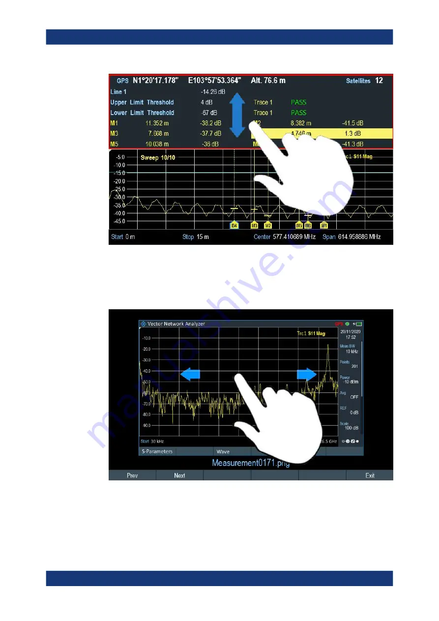
Preview Screenshot
Swipe horizontally to the left or right direction in the trace window to preview the
screenshot. Alternatively, select the "Prev" or "Next" softkey to preview the screenshot.
5.1.9
Skip Wizard Measurement
Swipe horizontally to the left direction to skip a wizard measurement. Alternatively,
select the "Skip" softkey to skip the measurement.
Touchscreen Gesture Element


