background image

Preparing for Use

R&S

®

TSMA6-BP

10

Getting Started 4900.9030.02 ─ 03

4.2


Inserting a Battery in the R&S TSMA6-BP

Only 

Li-ion

 battery of the type MNT_BP89WH (R&S No.1321.3772.00)

may be used.

The batteries are not charged on delivery. Before using the R&S TSMA6-
BP with TSMA6/TSME6, connect the TSMA6-BP (without a connected
TSME6 or TSMA6) to a DC power supply and charge the batteries com-
pletely.

The external recharging of the batteries is only allowed via a separate
charger (R&S TSMA6-BC4, 


R&S


No.


3630.7708.02 or R&S TSMA-BC2,

R&S


No.


1523.8015.02).

The R&S TSMA6-BP may be used only with closed battery cover.

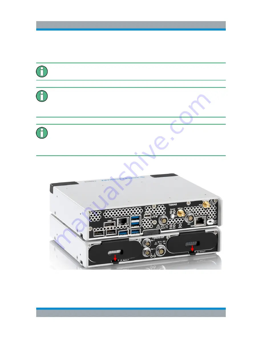
1. Open the covers of the battery bays.

Figure 4-1: Open battery cover

2. Insert the charged batteries.

The batteries can be inserted only the displayed orientation.

Inserting a Battery in the R&S TSMA6-BP

Summary of Contents for TSMA6-BP

Page 1: ...R S TSMA6 BP Battery Pack Unit Getting Started Getting Started Version 03 4900903002 a0èN2 ...

Page 2: ...one 49 89 41 29 0 Fax 49 89 41 29 12 164 Email info rohde schwarz com Internet www rohde schwarz com Subject to change Data without tolerance limits is not binding R S is a registered trademark of Rohde Schwarz GmbH Co KG Trade names are trademarks of the owners 4900 9030 02 Version 03 R S TSMA6 BP Throughout this manual products from Rohde Schwarz are indicated without the symbol e g R S TSMA6 is...
Page 3: ...s 7 4 Preparing for Use 8 4 1 Unpacking and Setting Up the Instrument 8 4 2 Inserting a Battery in the R S TSMA6 BP 10 4 3 Connecting the R S TSMA6 BP with External Power Supply 11 4 4 Connecting the R S TSMA6 BP with R S TSMA6 12 4 5 Connecting the R S TSMA6 BP with R S TSME6 14 5 Operation 17 5 1 Operation Modes 17 5 2 LED Display 17 5 3 Monitoring Battery Charge State 18 5 4 Battery Exchange Ho...

Page 4: ...Contents R S TSMA6 BP 4 Getting Started 4900 9030 02 03 ...

Page 5: ...ive and labo ratory environments Use the R S TSMA6 BP only for its designated purpose Observe the operating conditions and performance limits stated in the data sheet Where do I find safety information Safety information is part of the product documentation It warns you about the potential dangers and gives instructions how to prevent personal injuries or dam age caused by dangerous situations Saf...

Page 6: ... operations typical measurement examples and general information e g safety instructions etc A printed version is delivered with the instrument 2 2 Basic Safety Instructions Contains safety instructions operating conditions and further important informa tion The printed document is delivered with the instrument 2 3 Data Sheets and Brochures The data sheet contains the technical specifications of t...

Page 7: ...e measurement solution based on a battery powered system Key Features Power Supply for R S TSMA6 in portable applications Power Supply for up to 4 R S TSME6 devices Hot swap support for endless portable mode In bay charging feature with smart battery controller Charging display via LED and monitoring window SMBus interface with connected R S TSMA6 ...

Page 8: ...ons Notice that the data sheet may specify additional operating condi tions Risk of instrument damage during operation An unsuitable operating site or test setup can cause damage to the instru ment and to connected devices Ensure the following operating conditions before you switch on the instrument The instrument is dry and shows no sign of condensation The instrument is positioned as described i...

Page 9: ...material Packing material Retain the original packing material If the instrument needs to be transpor ted or shipped later you can use the material to protect the control ele ments and connectors Accessory list The following items are included with shipment of the R S TSMA6 BP 12 V DC IN power supply cable with a cigarette lighter adapter 4 x collar screw M2 5 screwed to the upper side of the R S ...

Page 10: ...hout a connected TSME6 or TSMA6 to a DC power supply and charge the batteries com pletely The external recharging of the batteries is only allowed via a separate charger R S TSMA6 BC4 R S No 3630 7708 02 or R S TSMA BC2 R S No 1523 8015 02 The R S TSMA6 BP may be used only with closed battery cover 1 Open the covers of the battery bays Figure 4 1 Open battery cover 2 Insert the charged batteries T...

Page 11: ...rs the following possibilities Operating connected TSMA6 TSME6 from the external power supply without draining the inserted batteries Using the R S TSMA6 BP unit as a power buffer for connected TSMA6 TSME6 in scenarios with cracking or shortly interrupted external DC power supplies e g in vehicles Charging inserted batteries when operating in Standalone Mode without an R S TSMA6 connected Connecti...

Page 12: ...be performed 1 Screw the collar screws 1 on the top of the R S TSMA6 BP with a Torx 8 screw driver Torque 0 66 Nm 0 05 Nm Figure 4 3 R S TSMA6 BP 1 Collar screws for connecting R S TSMA6 2 Power connector for R S TSMA6 3 Aux 1 Aux 2 4 DC IN 5 Status LEDs for battery 1 and 2 2 Remove the cover cap from the power connector of the R S TSMA6 Connecting the R S TSMA6 BP with R S TSMA6 ...

Page 13: ...S TSMA6 BP see Figure 4 3 4 Move the R S TSMA6 to the front side 2 until you hear a click when the con nectors are locked Figure 4 4 Connected R S TSMA6 Base Unit and R S TSMA6 BP 1 Attach R S TSMA6 base unit to R S TSMA6 BP 2 Move R S TSMA6 base unit to the front side 3 Power Connection established Connecting the R S TSMA6 BP with R S TSMA6 ...

Page 14: ...it lift the release button 1 on both sides of the R S TSMA6 base unit and slide it until the device is released 2 Figure 4 5 Disconnect devices 4 5 Connecting the R S TSMA6 BP with R S TSME6 1 Screw the collar screws 1 on the top of the R S TSMA6 BP with a Torx 8 screw driver Torque 0 66 Nm 0 05 Nm Connecting the R S TSMA6 BP with R S TSME6 ...

Page 15: ...for battery 1 and 2 2 Attach the R S TSME6 with the bottom side on top of the R S TSMA6 BP 3 Move the R S TSME6 to the back side until you hear a click when the con nectors are locked Figure 4 7 Connected R S TSME6 and R S TSMA6 BP 1 R S TSMA6 BP 2 R S TSME6 4 Connect the R S TSME6 DC IN with AUX1 or AUX 2 port of R S TSMA6 BP see Figure 4 6 with the related DC cable R S TSME ZYC R S No 1514 7290 ...

Page 16: ... to 4 R S TSME6 devices is possible In this case use two R S TSME ZYC cables connected to AUX 1 and AUX 2 Each of these cables is connected to 2 R S TSME6 devices Disconnect Device For disconnecting the devices see Disconnect Devices on page 14 Connecting the R S TSMA6 BP with R S TSME6 ...

Page 17: ...t is used without an R S TSMA6 The charging display is autonomous TSMA6 controlled Mode The R S TSMA6 controls the LED display via the SMBus interface 5 2 LED Display Figure 5 1 R S TSMA6 BP Status LEDs 1 P601 Status LED for battery 1 2 P602 Status LED for battery 2 Table 5 1 LED states and their meaning LED 1 and LED 2 in standalone mode Color LED State Comment OFF Battery 1 2 not present green B...

Page 18: ...e 10 Battery pow ered Critical charge blue BLINKING 2 Hz Charging state 10 External Power Charging green ON Battery 1 2 charg ing in progress External Power Charging fin ished green BLINKING 2 Hz Battery 1 2 charg ing completed Misc cyan BLINKING 5 Hz any other repor ted state e g bat tery error 5 3 Monitoring Battery Charge State When inserted in the bay of the R S TSMA6 BP the battery charging s...

Page 19: ... 5 3 R S TSMA6 BP Status LEDs 1 P601 Status LED for battery 1 2 P602 Status LED for battery 2 Via R S TSMA6 web GUI For details refer to R S TSMA6 Autonomous Mobile Network Scanner User Manual R S No 4900 8057 02 5 4 Battery Exchange Hot Swapping The batteries can be exchanged during powering the R S TSMA6 hot swap fea ture Battery Exchange Hot Swapping ...

Page 20: ...rged evenly Therefore when batteries enter low charge state it is recommended to replace both batteries In case of a hot swap do not exchange the batteries simultaneously 1 Open the cover of battery bay 1 Figure 5 4 Open cover 2 Remove the battery by the tab Battery Exchange Hot Swapping ...

Page 21: ... R S TSMA6 BP 21 Getting Started 4900 9030 02 03 Figure 5 5 Remove battery 3 Insert a charged battery 4 Close the cover of battery bay 1 5 Repeat step 1 to step 4 for battery bay 2 Battery Exchange Hot Swapping ...

Page 22: ...ted 4900 9030 02 03 Index B Brochures 6 D Data sheets 6 G Getting started 6 H Hot swap 19 L LED display 17 LED states standalone mode 17 TSMA6 controlled mode 18 O Operation mode Standalone 17 TSMA6 controlled 17 S Safety instructions 6 ...

Reviews: