R&S TSMA6-BP, Getting Started
The R&S TSMA6-BP user manual is a comprehensive guide for getting started with this advanced product. Offering step-by-step instructions and helpful tips, this manual is available for free download from our website, ensuring you have all the information you need at your fingertips to maximize the potential of your R&S TSMA6-BP.
Share
Download


Reviews:
No comments
Related manuals for TSMA6-BP
Edge
Brand: Garmin Pages: 32
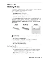
VERSA FX
Brand: NEC Pages: 10
Toughbook CF-29CTKGZKM
Brand: Panasonic Pages: 4
CF-VZSU47U
Brand: Panasonic Pages: 4
EB-U3300
Brand: Samsung Pages: 64
9839
Brand: Gardena Pages: 13
BC 18 V
Brand: Kärcher Pages: 96
E-1 - Digital Camera SLR
Brand: Olympus Pages: 2
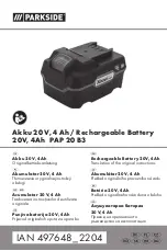
PAP 20 B3
Brand: Parkside Pages: 182
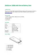
RP-PB41
Brand: Ravpower Pages: 2

evolion
Brand: Saft Pages: 42
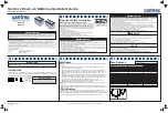
883-0105-12
Brand: Xantrex Pages: 2
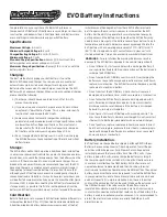
EVO
Brand: Ballistic Pages: 2
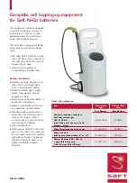
Ni-Cd
Brand: Saft Pages: 4
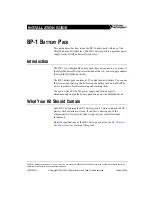
BP-1
Brand: National Instruments Pages: 4

RD-600
Brand: walimex Pages: 12
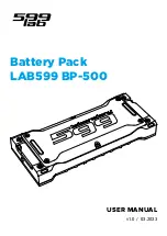
BP-500
Brand: Lab599 Pages: 12
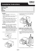
LP441s
Brand: Oki Pages: 4


