


Remote Control Commands
R&S
®
NRPxxS(N)
112
User Manual 1177.5079.02 ─ 10
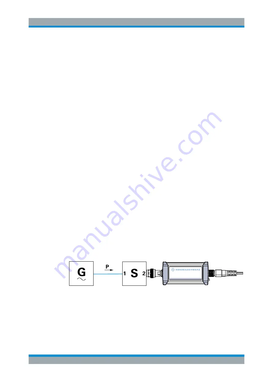
All R&S NRPxxS(N) power sensors allow compensating for the influence of any 2-port
device between the signal source and the sensor input. As a result, the firmware can
calculate the power that the signal source actually delivers. Examples of such 2-port
devices include attenuators, matching pads, minimum-loss pads and waveguide adapt-
ers. One precondition for such compensation is that you provide a complete set of S-
parameter data for the 2-port device in the frequency range required by the application.
The S-parameters of the attenuator delivered with the R&S NRPxxS(N) have been
measured by Rohde
&
Schwarz. The results of the factory calibration, including an S-
parameter table that matches the delivered attenuator, are stored in the factory calibra-
tion data set of the sensor. If you use this attenuator, its effect on the measurement is
compensated arithmetically.
Achieving Maximum Measurement Sensitivity
For maximum measurement sensitivity, you can choose from the following methods.
To operate the R&S NRPxxS(N) without an attenuator
► Disable the S-parameter correction:
● Each time after you have put the power sensor into operation.
[SENSe<Sensor>:]CORRection:SPDevice:STATe
.
● Permanently, using the S-Parameters tool.
See
Chapter 9.8.4.5, "Using the S-Parameters Tool"
To replace the delivered attenuator with any other 2-port device
1. Measure the S-parameters of the 2-port device.
2. Load the S-parameters into the power sensor.
In the user calibration data set of the power sensor, you can manage the S-param-
eters of several 2-port devices beside the S-parameters of the attenuator delivered
with the power sensor. The sensor can apply the sets of S-parameters individually,
depending on which S-parameter device you select as the active device.
3. Make sure that the S-parameter settings - selected S-parameter device, S-parame-
ter correction state - always match the used hardware configuration.
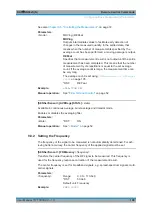
NRP
3-Path Diode Power Sensor
MHz to GHz, 100 pW to 200 mW (−70 dBm to +23 dBm)
SMART SENSOR TECHNOLOGY
Figure 9-7: Operation with 2-port device between signal source and sensor input
Configuring the S-Parameter Correction
[SENSe<Sensor>:]CORRection:SPDevice:LIST?
.............................................................. 113
[SENSe<Sensor>:]CORRection:SPDevice:SELect
.............................................................113
[SENSe<Sensor>:]CORRection:SPDevice:STATe
..............................................................113
Configuring Basic Measurement Parameters