Measurements and Results
R&S
®
FSVA3000/ R&S
®
FSV3000
199
User Manual 1178.8520.02 ─ 01
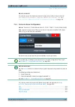
1. Press the "C/N" , "C/N0" softkey to configure the carrier-to-noise ratio measure-
ment.
2. To change the channel bandwidth to be analyzed, press the "Channel Bandwidth"
softkey.
3. To optimize the settings for the selected channel configuration, press the "Adjust
Settings" softkey.
4. To activate the measurements without reference to the bandwidth, press the "C/N"
softkey.
To activate the measurements with reference to the bandwidth, press the "C/N
0
"
softkey .
5. If the carrier signal is located within the analyzed channel bandwidth, switch off the
carrier signal so that only the noise is displayed in the channel and perform a sec-
ond measurement.
The carrier-to-noise ratio is displayed after the measurement has been completed.
7.5
Occupied Bandwidth Measurement (OBW)
An important characteristic of a modulated signal is its occupied bandwidth, that is: the
bandwidth which must contain a defined percentage of the power. In a radio communi-
cations system, for instance, the occupied bandwidth must be limited to enable distor-
tion-free transmission in adjacent channels.
........................................................................................199
............................................................................................... 202
How to Determine the Occupied Bandwidth
......................................................... 204
......................................................................................... 205
7.5.1
About the Measurement
The occupied bandwidth is defined as the bandwidth containing a defined percentage
of the total transmitted power. A percentage between 10 % and 99.9 % can be set.
Measurement principle
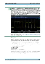
The bandwidth containing 99% of the signal power is to be determined, for example.
The algorithm first calculates the total power of all displayed points of the trace. In the
next step, the points from the right edge of the trace are summed up until 0.5 % of the
total power is reached. Auxiliary marker 1 is positioned at the corresponding frequency.
Then the points from the left edge of the trace are summed up until 0.5 % of the power
is reached. Auxiliary marker 2 is positioned at this point. 99 % of the power is now
between the two markers. The distance between the two frequency markers is the
occupied bandwidth which is displayed in the marker field.
Occupied Bandwidth Measurement (OBW)

