Interfaces and Connectors
R&S
®
DVMS1
13
Getting Started 2113.7619.02 ─ 12
3
Interfaces and Connectors
This chapter describes the front panel and the rear panel of the instrument, including
all status displays and connectors.
Some connectors warm up slightly when high voltages are applied. As long as maxi-
mum input levels are not exceeded, warm-up does not affect normal operation.
3.1
Front Panel
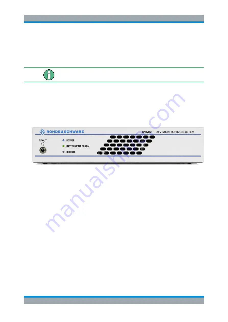
This chapter gives a short overview of the status displays and connectors on the front
panel.
The inscriptions on your R&S
DVMS match the captions of the connector descriptions.
Figure 3-1: Front panel view
3.1.1
Status Display LEDs
The basic status is indicated by LEDs.
3.1.1.1
POWER
Displays the power supply status.
●
LED off: No power is supplied. R&S
DVMS is switched off.
●
LED blue: Power is supplied.
●
LED red (flashing): Failure of fan.
To rectify this failure, switch the R&S
DVMS off and on again. If the fan still does
not work, shut down the R&S
DVMS to prevent overheating of the R&S
DVMS and
contact one of our customer support centers.
Further information:
●
Chapter 3.2.1, "AC Power Supply Connector"
Front Panel


