OM-WORK TOP/UNDERCOUNTER SERIES 7
Installation
SELECTING A LOCATION FOR YOUR NEW UNIT
The following conditions should be considered when selecting a location for your unit:
1.
Floor and Countertop Load:
The area on which the unit will rest must be level, free
of vibration, and suitably strong enough to support the combined weights of the unit
plus the maximum product load weight.
2.
Clearance
: Clearance must be a combined total of at least 1” on back of unit and
open clearance at the top. Do not place any object that can block the ventilation
exhaust from the machine compartment register. Area of equipment must be free of
all combustible materials.
3.
Ventilation
: The air cooled self contained unit requires a sufficient amount of cool
clean air. Avoid surrounding your unit around other heat generating equipment and
out of direct sunlight. Also, avoid locating in an unheated room or where the room
temperature may drop below 70°F or rise above 100°F.
INSTALLATION CHECKLIST
After the final location has been determined, refer to the following checklist prior to
start-up:
1. Check all exposed refrigeration lines to ensure that they are not kinked, dented, or
rubbing together.
2. Check that the condenser and evaporator fans rotate freely without striking any
stationary members.
3. Unit must be properly leveled; check all legs or casters to ensure they all are in
contact with the floor while maintaining a level work surface. Adjusting bullet
feet heights or shimming casters may be necessary if the floor is not level. NOTE:
Damage to equipment may result if not followed. Unified Brands is not responsible
for damage to equipment if improperly installed.
4. Allow unit time to cool down to temperature. If temperature adjustments are required,
the control is located on the front panel. Confirm that the unit is holding the desired
temperature.
5. Refer to the front of this manual for serial number location. Please record this
information in your manual on page 3 now. It will be necessary when ordering
replacement parts or requesting warranty service.
6. Before putting in food, allow your unit to operate for approximately two (2) hours so
that interior of the unit is cooled down to storage temperature.
7. Check drawer to ensure the drawer slides freely and fully extends along with seating
into the cabinet properly when closed.
ELECTRICAL SUPPLY
Any wiring should be done by a qualified electrician in accordance with all national and
local electrical codes. A properly wired and grounded outlet will assure proper operation.
Please consult the data tag attached to the compressor to ascertain the correct electrical
requirements. Supply voltage and amperage requirements are located on the serial
number tag (see page 3 for location).
CAUTION!
THIS UNIT CONTAINS R290 FLAMMABLE
REFRIGERANT. USE CAUTION WHEN
HANDLING MOVING AND USE OF THE
REFRIGERATOR OR FREEZER. AVOID
DAMAGING THE REFRIGERANT TUBING OR
INCREASE THE RISK OF A LEAK.
FAILURE TO FOLLOW INSTALLATION
GUIDELINES AND RECOMMENDATIONS MAY
VOID THE WARRANTY ON YOUR UNIT.
IT IS IMPORTANT THAT YOUR UNIT HAS
ITS OWN DEDICATED LINE. CONDENSING
UNITS ARE DESIGNED TO OPERATE WITH
A VOLTAGE FLUCTUATION OF PLUS OR
MINUS 10% OF THE VOLTAGE INDICATED
ON THE UNIT DATA TAG. BURN OUT OF A
CONDENSING UNIT DUE TO EXCEEDING
VOLTAGE LIMITS WILL VOID THE WARRANTY.
THE DANFOSS CONTROLLER HAS LOW
VOLTAGE PROTECTION AND WILL NOT
OUTPUT VOLTAGE TO THE COMPRESSOR IF
VOLTAGE IS LESS THAN 104V.
THIS UNIT IS INTENDED FOR USE IN
LABORATORIES IN COMMERCIAL,
INDUSTRIAL, OR INSTITUTIONAL
OCCUPANCIES AS DEFINED IN THE SAFETY
STANDARD FOR REFRIGERATION SYSTEMS,
ASHRAE 15.
Summary of Contents for 9404F-290
Page 5: ...OM WORK TOP UNDERCOUNTER SERIES 5 EXTERIOR OF UNIT NEAR EXPOSED REFRIGERANT TUBING Labeling...
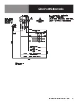
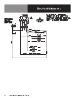
Page 18: ...18 OM WORK TOP UNDERCOUNTER SERIES Electrical Schematic...
Page 19: ...OM WORK TOP UNDERCOUNTER SERIES 19 Electrical Schematic...
Page 20: ...20 OM WORK TOP UNDERCOUNTER SERIES Electrical Schematic...
Page 21: ...OM WORK TOP UNDERCOUNTER SERIES 21 Electrical Schematic...
Page 22: ...22 OM WORK TOP UNDERCOUNTER SERIES Electrical Schematic...
Page 55: ......


