
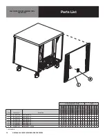
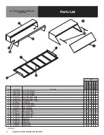


4
OM-9000-290 SERIES REFRIGERATORS/FREEZERS
SERVICE
CAUTION: COMPONENT PARTS SHALL BE REPLACED WITH FACTORY OEM PARTS.
SERVICE WORK SHALL BE DONE BY FACTORY AUTHORIZED SERVICE
PERSONNEL, SO AS TO MINIMIZE THE RISK OF POSSIBLE IGNITION DUE TO
INCORRECT PARTS OR IMPROPER SERVICE.
CAUTION: BEFORE MAKING ANY REPAIRS, ENSURE THE UNIT IS DISCONNECTED
FROM ITS POWER SOURCE.
This piece of equipment uses a R290 Refrigeration system. This equipment has
been clearly marked on the serial tag the type of refrigerant that is being used.
There is also a warning labels stating that the unit contains R290 refrigerant. R290
is safe to use as long as you follow these warning labels and some.
No smoking or open flames when servicing this equipment. If needed, use a CO2
or dry=power type fire extinguisher
Replacement parts used on any R290 Refrigeration system cabinet must have
specific UL certification for non-sparking components.
Only authorized service technician, certified in R290 system should service this
equipment.
MANIFOLD SET
A R134A manifold set can be used for servicing this equipment.
REFRIGERANT RECOVERY
Follow all national and local regulations for R-290 refrigerant recovery.
LEAKING CHECKING AND REPAIR
Leak check an R-290 system the same way you would an R-134a or R-404A
system with the following exceptions.
1. Do not use a Halid leak detector on a R290 system.
2. Electronic leak detector must be designated specifically for combustible gas.
Use of a bubble solution or an ultrasonic leak detector are acceptable.
When repairing a leak, it is recommended using oxygen free dry nitrogen with a
trace gas not exceeding 200PSI.
When accessing an R290 system, piercing valves are not to remain on the
equipment in a permanent manner. After charge is recovered, Schrader valves
are to be installed on the process stubs. Proper charge is to be weighed into the
system and the system is to be leak checked afterwards.
The R290 equipment must have red process tubes and other devices through
which the refrigerant is serviced, such as any service port. This color marking
must remain on the equipment. If marking is removed, it must be replace and
extend at least 2.5 centimeters (1”) from the compressor.
CHARGING
Follow the charge amount specified on the data tag. It is recommended to use the
shortest hoses possible to prevent undercharging.
• Ensure the system is sealed and leak checked
• Evacuate system to a minimum 500 micron
• Weigh in correct charge
• Leak check the system again
• Bleed the refrigerant from the high side hose to the low side hose
• Disconnect the hoses
• Remove line taps
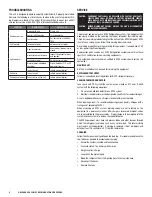
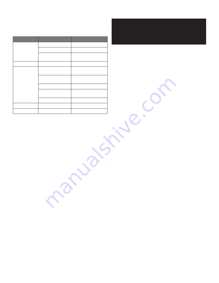
TROUBLESHOOTING
This unit is designed to operate smoothly and efficiently if properly maintained.
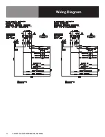
However, the following is a list of checks to make in the event of a problem. Wir-
ing diagrams are found at the end of this manual. When in doubt, turn unit off
and contact service at 888-994-7636 or [email protected].
SYMPTOM
POSSIBLE CAUSE
PROCEDURE
Unit does not run
No power to unit
Plug in unit
Control in OFF position
Turn controller on
Faulty control
Call for service at 888-994-
7636
Unit too cold
Incorrect set point
Adjust control set point
Unit too warm
Door / drawer ajar
Ensure door / drawer is fully
closed
Gasket torn or out of place
Inspect the gasket for wear
and position
Incorrect set point
Adjust control set point
Warm product introduced
to cabinet
Pre-chill product 37ºF or 3ºF
degree for freezer
Ice on the coil
Initiate manual defrost
Unit noisy
Ice on the coil
Initiate manual defrost
Unit does not defrost Excessive ice on the coil
Initiate manual defrost


