background image


15 

FINAL CHECKS & ADJUSTMENTS 

 
1)


  Turn  the  front  wheels  completely  left  then 

right.    Verify  adequate  tire,  wheel,  and  brake  hose 
clearance.    Inspect  steering  and  suspension  for 
tightness and proper operation. 
 
2)


  With  the  suspension  at  maximum  extension 

(full  droop),  inspect  and  rotate  all  axles  and  drive 
shafts.    Check  for  binding  and  proper  slip  yoke 
insertion.  The slip yoke should be inserted a minimum 
of one inch into the transfer case and/or transmission. 
 
3)


  Ensure  that  the  vehicle  brake  system  operates 

correctly.    If  new  brake  hoses  were  installed,  verify 
that each hose allows for full suspension movement. 
 
4)


 Readjust headlamps.  Have vehicle Aligned at 

a certified alignment facility. 
 

Recommended Alignment Specifications 

Caster (degrees):  4.5° ± 1.0° 
Camber (degrees):  0° - neg .3° 
Sum Toe In (degrees):  .1° ± .2° 
 
Please  retain  this  publication  for  future  reference.  
See Important Note Q. 


Summary of Contents for RS6583B

Page 1: ...88583 Rev E Suspension System RS6583B 2013 2007 Chevrolet Silverado GMC Sierra 1500 88583 Rev E...

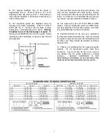
Page 2: ...Each hardware kit in this system contains fasteners of high strength and specific size Do not mix hardware kits or substitute a fastener of lesser strength See bolt identification table on page 2 G Co...

Page 3: ...D vehicle omit steps pertaining to the front axle assembly Also follow the specific 2WD steps for aft brace installation R Important information for the end user is contained in the consumer installer...

Page 4: ...4 RS6583B Suspension System...

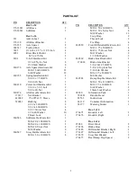
Page 5: ...140 HHCS 2 M16 2 0 x 120 HHCS 2 M16 2 0 Stover Nut 4 M16 Washer 8 860547 Sway Bar Hardware Kit 1 M10 1 50 x 30 HHCS 4 P N DESCRIPTION QTY M10 1 50 x 60 HHCS 4 M10 1 50 x Nyloc Nut 4 M10 Washer 12 Loop...

Page 6: ...at the frame rail See illustration 2 Illus 2 NOTE For vehicles equipped with Electronic Suspension Control Autoride separate brake hose from sensor link bracket 2 Remove the brake caliper anchor bolts...

Page 7: ...metal 3 Reference mark the front drive shaft U joint to the differential yoke Remove the bolts and retainers from the yoke and slide the shaft rearward to disengage Tape the bearing cap assemblies and...

Page 8: ...t U joint to the differential yoke Tighten bolts to 22 ft lbs SUBFRAME INSTALLATION 1 Using a round file enlarge the inside corners of both lower control arm front brackets See illustration 7 Illus 7...

Page 9: ...lign flange marks and place the half shaft flange against the spacer Apply thread lock to bolts and attach the half shaft to the differential with the hardware from kit 860176 See illustration 10 Tigh...

Page 10: ...y bar to the lower control arms with the original end link assemblies BRAKE HOSE INSTALLATION 1 Install the brake rotor Apply thread lock and attach the caliper to the knuckle with the original mounti...

Page 11: ...3 Loosely attach the aft braces to subframe 176385B with the hardware from kit 860474 See illustration 16 NOTE Both aft braces should angle slightly outward from front to rear 4 If applicable remove...

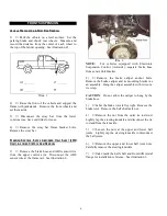
Page 12: ...ighten the sway bar end link bolts to 22 ft lbs REAR SUSPENSION ADD A LEAF RISER BLOCK INSTALLATION 1 Chock front wheels Raise the rear of the vehicle and support the frame with jack stands Remove the...

Page 13: ...hole in the axle pad Place the new riser block 15080 on the axle pad with the taller end of the block in the rear and the top hole offset to the front See illustration 21 Illus 21 NOTE Ignore the up...

Page 14: ...1 and 2 for the other side 4 Install rear wheels and lower vehicle to ground Tighten lug nuts to 140 ft lbs BRAKE LINE BRACKET INSTALLATION 1 Attach the new brake line bracket 170014 to the rear diffe...

Page 15: ...r slip yoke insertion The slip yoke should be inserted a minimum of one inch into the transfer case and or transmission 3 Ensure that the vehicle brake system operates correctly If new brake hoses wer...

Reviews: