background image

R146 

 24 


FR146 2 Meter FM Receiver Kit 
Quick Reference Page Guide 


I

ntroduction to the FR146 ............... 4 

Circuit Description .......................... 5 
Parts List ........................................ 6 
Simplified Block Diagram ............... 8 
Parts Layout Diagram .................... 9 
FR146 Assembly Instructions ........10 
Testing and Alignment ...................18 
Enclosure Ideas ..............................20 
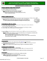
Troubleshooting Guide ...................21 
Notes for Advanced Users .............21 
Ramsey Kit Warranty .....................23 

Price: $5.00 
Ramsey Publication No. FR-146 
Assembly and Instruction manual for: 

RAMSEY MODEL NO. FR146  2 METER FM RECEIVER KIT


REQUIRED TOOLS


Soldering Iron Ramsey WLC100 

Thin Rosin Core Solder  Ramsey RTS12 

Needle Nose Pliers  Ramsey MPP4 or 
RTS05 

Small Diagonal Cutters  Ramsey RTS04 

<OR> Technician’s Tool Kit  TK405 
 

ADDITIONAL SUGGESTED ITEMS


Holder for PC Board/Parts  Ramsey HH3  

Desoldering Braid  Ramsey RTS08 

Digital Multimeter  Ramsey M133 

TOTAL SOLDER POINTS 

232 

ESTIMATED ASSEMBLY 

TIME 

Beginner ............... 6.8 hrs 
Intermediate ......... 3.9  hrs 
Advanced ............. 2.9  hrs 

Summary of Contents for FR146

Page 1: ...1 uV sensitivity Tuned input low noise preamp stage True Dual conversion superhet design with 2 pole Ceramic High IF and 6 pole Ceramic low IF filters Front Panel Volume Squelch and Tuning controls E...

Page 2: ...SEY AMATEUR RADIO KITS HR Series HF All Mode Receivers QRP Series HF CW Transmitters DDF1 Doppler Direction Finder CPO3 Code Practice Oscillator QRP Power Amplifiers RAMSEY MINI KITS Many other kits a...

Page 3: ...o the FR146 4 Circuit Description 5 Parts List 6 Simplified Block Diagram 8 Parts Layout Diagram 9 FR146 Assembly Instructions 10 Schematic Diagram 12 Testing and Alignment 18 Enclosure Ideas 20 Troub...

Page 4: ...eceiver to take on trips keep in a briefcase or to watch for band openings Before beginning the project or even studying the circuit description it is worthwhile to develop some prior respect for how...

Page 5: ...D1 and varied by R1 The output from pin 4 of the SA602 passes through a ceramic 10 7 MHz filter amplified by transistor Q2 and applied to input pin 18 of U2 Q3 provides AFC Automatic Frequency Control...

Page 6: ...black square FL2 Fixed Resistors 1 2 ohm red black gold R22 3 270 ohm red violet brown R6 9 20 1 470 ohm yellow violet brown R5 2 1K ohm brown black red R11 12 3 10K ohm brown black orange R7 17 19 1...

Page 7: ...subminiature 2 5 mm 3 32 audio output jack which mates with commonly available earphone plugs and adapters available at Radio Shack such as 274 290 plug or 274 327 adapter for 1 8 mono plug If you pr...

Page 8: ...FR146 8 U2 3359 FR146 BLOCK DIAGRAM U1 SA602 MIXER...

Page 9: ...FR146 9 FR146 PARTS LAYOUT DIAGRAM...

Page 10: ...component 5 Trim or nip excess wire lengths after soldering NOTE Save some of the longer wire scraps nipped from resistors and capacitors These will be used to form wire jumpers JMP1 etc to be soldere...

Page 11: ...mum amount of wire lead is exposed above the board In soldering don t be afraid to use enough heat to make good clean connections 13 Install R4 47K yellow violet orange just to the left of Q1 14 Insta...

Page 12: ...FR146 12...

Page 13: ...FR146 13...

Page 14: ...the PC board for mechanical stability which directly affects the frequency stability of the receiver Make good solid solder connections 27 Install C12 8 2 pF 28 Install varactor diode D1 marked BB505...

Page 15: ...LS 36 Install Q2 a 2N3904 transistor Correctly position the flat side 37 Install R13 47K ohms yellow violet orange 38 Install C20 001 uf marked 001 or 102 39 Install R12 1K ohms brown black red 40 Ins...

Page 16: ...yout diagram Solder each of the 18 connections carefully Make sure you have good lighting as well as good technique to make sure that no solder bridges flow between the connections 62 Install C22 100...

Page 17: ...33 100 to 220 uF electrolytic observe polarity 80 Install the battery snap terminal in the two holes below S1 making sure that the positive red lead is inserted into the hole on the PC board 81 The ba...

Page 18: ...rified reliable reception of your regional NOAA station adjustment to your desired listening range will become easier 2 L3 Alignment Tool If you do not already have a set of plastic or nylon coil alig...

Page 19: ...s without an antenna connected You can expect to monitor local repeater and simplex transmissions easily using a simple groundplane style antenna The receiver also responds very well to the addition o...

Page 20: ...ght be planning to combine several Ramsey circuit boards in a single enclosure Use of the inexpensive and attractive Ramsey case and knob kit will give your unit that finished look and increase its re...

Page 21: ...s Further signal path tracing may be necessary to find your problem Problem Very weak signals If Q1 is defective or incorrectly installed very little signal energy will reach the NE602 If Q2 is defect...

Page 22: ...rolled oscillator configurations was written by Michael A Covington with acknowledged assistance from Signetics personnel published with good circuit illustrations in Radio Electronics magazine for Ap...

Page 23: ...h be assured that the 1K ohm resistors are actually the missing 10 K parts Hum m m I guess the red band really does look orange Ramsey Electronics project kits are packed with pride in the USA If you...

Page 24: ...e 5 00 Ramsey Publication No FR 146 Assembly and Instruction manual for RAMSEY MODEL NO FR146 2 METER FM RECEIVER KIT REQUIRED TOOLS Soldering Iron Ramsey WLC100 Thin Rosin Core Solder Ramsey RTS12 Ne...

Reviews: