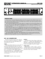
background image

FR-10 

?

 8 

U2, 3359


FR-10 BLOCK DIAGRAM 

FR-10 

?

 21 

ALIGNMENT PROCEDURE  
 

?

1.    Make sure the power switch is off. 

?

2.    Connect the antenna, earphone or speaker and battery. 

?

3.    Turn the slug of L3 until it is even with top of coil form. 

?

4.    Now, turn the slug of L3 clockwise 7 turns back into the form. 

?

5.    Turn the slug of L4 until it is flush with the top of the coil and 
       then turn it 2 turns back into the coil. 

?

6.    Turn all three controls to the left, fully counterclockwise. 

?

7.    Turn the power ON.  

?

8.    Turn R2 (Volume control) until you hear some noise. 

?

9.    Adjust L4 for maximum noise in the speaker. Further alignment 
       now consists of adjusting the oscillator coil L3 to permit the 
       tuning control (R3) to cover the 5 MHz segment between 25 and 
       35 MHz of primary interest to you.  

 
If you are a beginner with no license or other equipment, any Ham 
operator with a 10-meter transceiver should be willing to give you the 
test signal and extra help that you need. The FR-10 is very sensitive, so 
operate the transceiver on low power on a simplex frequency from a 
distance of at least across the room. An 8" piece of wire will be a 
sufficient receiving antenna for such tests. If you don't know any Hams, 
visit a friendly two-way radio service center to get close to the test signal 
you need! If ham radio or 10 meters is new to you and you do not have 
a general coverage receiver for comparison, here's a listing of the 
various band portions:    
             28.00 - 28.10   General class and higher CW 
             28.10 - 28.30   Novice & Tech CW and digital 
             28.30 - 28.50   Novice & Tech SSB 
             28.50 - 29.70   General class and higher SSB, FM, etc. 
             29.30 - 29.50   Amateur satellites  
             29.52 - 29.58   Repeater inputs  
             29.60                Simplex calling frequency 
             29.62 - 29.68   Repeater outputs - This is where you'll hear the    
             most action! 
 

Summary of Contents for FR-10

Page 1: ...64 TOTAL SOLDER POINTS 232 ESTIMATED ASSEMBLY TIME Beginner 6 8 hrs Intermediate 3 9 hrs Advanced 2 9 hrs FR 10 1 10 METER FM RECEIVER KIT Ramsey Electronics Model No FR 10 Check out the 10 meter acti...

Page 2: ...s in suitable condition for testing Please be aware that testing can usually determine if the part was truly defective or damaged by assembly or usage Don t be afraid of telling us that you blew it we...

Page 3: ...EIVER KIT Ramsey Publication No MFR 10 Price 5 00 TABLE OF CONTENTS Introduction to the FR 10 4 Circuit Description 5 Parts List 6 Simplified Block Diagram 8 Parts Layout Diagram 9 FR 10 Assembly Inst...

Page 4: ...rs and diodes And in addition to four inductors a FR 10 25 receivers do not offer much PC board space or real need for customization or other modifications These receivers do what they are intended to...

Page 5: ...e Ramsey HF receivers and transmitters the FR series of VHF FR 10 5 crystal and two ceramic filters there are nearly 60 capacitors and resistors Surely all that should result in a decent receiver You...

Page 6: ...your receiver on for a few days just like we leave our computers and Ham or computer accessories on all the time 2 We thought you d have more fun planning and installing your own lamp that glows in t...

Page 7: ...t way to make a good installation is to drill a neat hole just slightly smaller than the diameter of the LED Then enlarge the hole a little bit at a time just enough to let the LED be pressed in and h...

Page 8: ...beginner with no license or other equipment any Ham operator with a 10 meter transceiver should be willing to give you the test signal and extra help that you need The FR 10 is very sensitive so oper...

Page 9: ...nd to the point Good test bench signal sources include your own 10 meter transceiver if you are licensed to use it a signal generator or grid dip oscillator 2 L3 Alignment Tool If you do not already h...

Page 10: ...fresh battery earphone or speaker with correct plug or adapter 76 Review the instructions for installing U1 and U2 Insert U3 the LM386 IC with the band or dot oriented correctly Solder the 8 connecti...

Page 11: ...n As You Build KIT ASSEMBLY We have a twofold strategy for the order of the following kit assembly steps First we install parts in physical relationship to each other so there s minimal chance of inse...

Page 12: ...facing to the right toward the middle of the board Press the transistor snugly into the PC board so that only a minimum amount of wire lead is exposed above the board When soldering don t be afraid to...

Page 13: ...70 ohms yellow violet brown 2 NE602 OSCILLATOR MIXER and VARACTOR TUNING 16 Install R6 270 ohms red violet brown 17 Install C7 a 001 uF bypass capacitor marked 001 102 or 1 nF In installing the NE602...

Page 14: ...FR 10 14 FR 10 15...

Reviews: