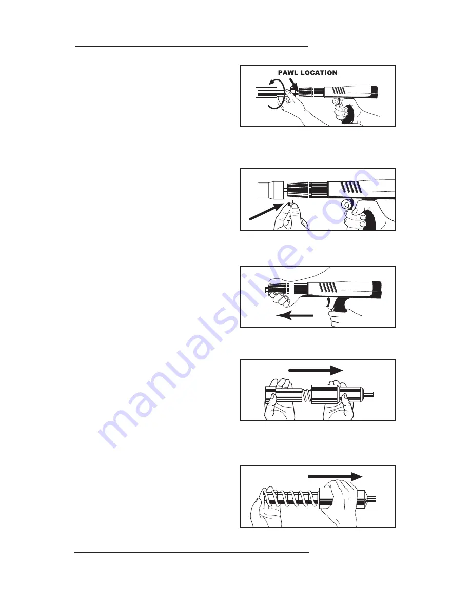
RAMSET RT400 M Operator'S Safety & Operating Instruction Manual Download Page 15

TOOL DISASSEMBLY

1. Unscrew the barrel retention sleeve 

and slide it away from the tool housing.
Handle the tool carefully after the
sleeve is unscrewed to prevent the 
two barrel pawls from falling out.

2. Remove the two pawls from the slots 

in the sides of the tool housing while
holding the retention sleeve forward
toward the muzzle end of the tool.

3. Slide the barrel assembly out of the tool

body. Note the position of the slots on
the side of the barrel and the rod at the
lower rear of the barrel. Also note the
position of the power adjust hole.

4.  Remove the retaining sleeve.

5. Remove the return spring.

UNSCREW THE BARREL 

RETAINING SLEEVE

REMOVE BOTH PAWLS

SLIDE BARREL ASSEMBLY

OUT OF THE TOOL BODY

REMOVE THE RETAINING SLEEVE

REMOVE THE RETURN SPRING

DISASSEMBLY

15

DISASSEMBLY 

Summary of Contents for RT400 M

Page 1: ...RATOR S SAFETY OPERATING INSTRUCTION MANUAL DANGER THIS TOOL FOR USE BY LICENSED OPERATORS ONLY READ AND OBEY ALL SAFETY AND OPERATING INSTRUCTIONS BEFORE OPERATING TOOL SEMI AUTOMATIC LOW VELOCITY PISTON TYPE FASTENING TOOL ...

Page 2: ... the safe and proper use of this tool rests with the tool user and the employer SAFETY INTRODUCTION DANGER THIS TOOL IS TO BE USED ONLY BY PROPERLY TRAINED AND LICENSED OPERATORS YOU MUST SUCCESSFULLY COMPLETE THE ITW RAMSET RED HEAD S TRAINING PROGRAM FOR THE TOOL AND OBTAIN A CERTIFIED OPERATOR S LICENSE BEFORE HANDLING LOADING OR OPERATING THIS TOOL ATTEMPTING TO HANDLE OR OPERATE THIS TOOL WIT...

Page 3: ...ver fasten into any base material that does not pass the Center Punch test Failure to assure the suitability of the base material can result in serious injury to the eyes or other body parts Center Punch Test ALWAYS WEAR SAFETY GOGGLES WHEN PERFORMING THIS TEST 1 Always check the material being fastened into for hardness before attempting any fastening operation 2 Using a fastener as a center punc...

Page 4: ...s keep the work area clear of bystanders and unnecessary materials that could interfere with safe tool operation Operating the tool in a congested or cluttered area may affect your ability to operate the tool safely 3 Never operate tool if flammable or explosive materials are nearby Powder loads burn and create sparks when fired and could ignite these materials or fumes 4 Always post warning signs...

Page 5: ...by either a fastener or the tool piston should the tool be accidentally fired 6 Always store the tool unloaded and keep the tool and the loads securely locked in a tool box Keep keys away from children and unlicensed persons 7 Always keep the tool pointed away from yourself and others 8 Never carry a loaded tool around the work area 9 Never allow anyone not trained to use the tool 10 Never engage ...

Page 6: ...s ALWAYS FOLLOW THE MISFIRE PROCEDURE If the tool does not fire after pulling the trigger continue to hold the depressed tool against the work surface for at least 30 seconds Then carefully open the tool remove the load strip and put it in a can of water or other non flammable liquid Never carelessly discard a strip with live loads into a trash container If the tool becomes stuck or jammed with a ...

Page 7: ...level first If more power is required to set the fastener use the next higher power level until the powder level necessary to drive the fastener is reached RS27 10 SHOT STRIP LOAD POWER CATALOG LOAD CASE LEVEL NUMBER COLOR COLOR 2 2RS27 Brown Brass 3 3RS27 Green Brass 4 4RS27 Yellow Brass 5 5RS27 Red Brass 300 HEAD PLASTIC FLUTED DRIVE PINS 145 Shank Diameter in Shank Lengths from 1 2 to 1 1 2 300...

Page 8: ... a sill plate application where by necessity the edge distance is reduced Driving fasteners too close to an edge or too close to each other can cause the concrete edge to fail or fasteners to fly free Fastening to Concrete Block or to Masonry Walls While this application is not recommended when used it is necessary to take care to observe a 3 edge distance to avoid cracking the block and over pene...

Page 9: ...ce the fastener point out into the muzzle end of the tool until the point end is inside the muzzle NEVER load a fastener with your finger on the trigger DO NOT use excessive force when inserting a fastener STOP immediately if excessive force is require inspect the barrel to find out why the fastener is not entering the muzzle freely DO NOT continue loading unless the problem is corrected 3 With th...

Page 10: ...the tool 6 Insert another fastener in the muzzle end of the tool as before and the tool is ready for the next fastening Keep your finger off of the trigger until the tool is in position to drive the fastener 7 To remove a used or partially used strip load from the tool pull the strip out from the top of the tool NEVER try to remove a jammed or stuck load strip Should a jammed load strip occur call...

Page 11: ...or improper assembly Reduction or loss of power Piston not being returned Check to be sure that the to the full rear position return spring has pulled the barrel completely open to properly position the piston Worn or damaged retention Replace missing worn or balls or clip on the buffer damaged parts assembly Worn or broken pawls Replace pawls Tool cannot be cocked Excessive dirt buildup Clean too...

Page 12: ...PARTS SCHEMATIC PARTS SCHEMATIC 12 For Magazine Schematic and Parts Lists see page 14 ...

Page 13: ...2 A1067 FIRING PIN SPRING 1 13 A1063 ADVANCE LINK ASSEMBLY 1 14 A1068 ADVANCE LEVER ASSEMBLY PIN 1 15 A1045 ADVANCE LEVER ASSEMBLY RETENTION NUT 1 16 A1094 MECHANISM HOUSING 1 17 A1095 MECHANISM HOUSING PLUG 1 18 A1089 COCKING ROD 1 19 A1088 ROTARY SEAR 1 20 A1069 COCKING ROD SPRING 1 21 A1100 END CAP SCREW WASHER PACKAGE 2 22 A1060 TRIGGER MECHANISM PIN 1 23 A1074 TRIGGER SPRING 1 24 A1061 PLASTI...

Page 14: ...sively Complete disassembly and cleaning of all parts may be necessary to restore the tool to normal operation General maintenance should be performed every six months or more often if the tool is subjected to heavy use Contact your authorized Ramset Distributor for assistance IMPROPERLY MAINTAINED TOOLS CAN CAUSE SERIOUS INJURIES TO TOOL OPERATOR AND BYSTANDERS CLEAN TOOL DAILY ALWAYS FUNCTION TE...

Page 15: ...retention sleeve forward toward the muzzle end of the tool 3 Slide the barrel assembly out of the tool body Note the position of the slots on the side of the barrel and the rod at the lower rear of the barrel Also note the position of the power adjust hole 4 Remove the retaining sleeve 5 Remove the return spring UNSCREW THE BARREL RETAINING SLEEVE REMOVE BOTH PAWLS SLIDE BARREL ASSEMBLY OUT OF THE...

Page 16: ...N CLEANING TOOL PARTS 9 Check the piston tip for mushrooming or other deformities and grind flat The tip of the piston must be 90 to the shank and grinding must only be done by qualified personnel The overall minimum length of the piston must not be less than 6 1 8 When less than this length the piston must be replaced to avoid tool damage 10 Reassemble the tool in the reverse order of disassembly...

Page 17: ...e further detailed on page 15 3 Rotate the barrel and magazine so the square holes in the side of the magazine line up with the slots in the magazine collar 4 Place the pawls into the square holes in the magazine With the fastening end of the barrel pointed away from you turn the barrel counter clockwise to remove it from the magazine assembly 5 The magazine can be installed by following the rever...

Page 18: ...right 2005 ITW Ramset Red Head POWDER ACTUATED TOOL MANUFACTURES INSTITUTE INC TM Concrete Fastening Systems Wood Dale IL 60191 630 350 0370 www ramset redhead com Buy with Confidence Buy From Your Authorized Distributor ILLINOIS TOOL WORKS 2005 PRINTED IN THE U S A REVISED 01 05 Form No SMRT400A 01 05 THE MODEL RT400 TOOL COMPLIES WITH OSHA REQUIREMENTS AND WITH ANSI A10 3 SPECIFICATIONS FOR TOOL...

Reviews: