


The Power switch must always be on
the “Off” position before plugging the
amp to a properly earthed mains sock-
et. The colour code is:
Blue: Neutral
Brown: Live, single phase
Yellow-green: Protective Earth
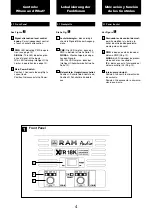
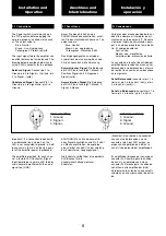
The input signal fed to the amplifier can
be either balanced or un-balanced. The
drawing below describes both ways to
wire an XLR connector for the purpose.
Balanced Signal:
Connect pin 1 to
Ground, pin 2 to (hot) and pin
3 to Signal - (cold).
Unbalanced Signal:
Connect Pin 1 to
Ground, pin 2 to Signal and pin 3 to
Ground.
Important!: If a connection is done with
a un-balanced line and pin 3 on the
XLR is not connected to ground, a 6 dB
loss occurs in the line and only a quar-
ter of the amplifier power is produced.
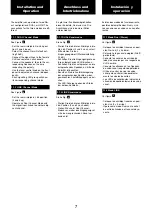
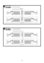
The amplifiers provides, for each chan-
nel, a female XLR Connector (Signal
Input) paralleled to a male XLR to daisy
chain several amplifiers with the same
signal line (LINK).
3.1 Connections
Bevor Sie diese Einheit an eine
SHUKO-Steckdose anschließen, schal-
ten Sie den Hautstromschalter aus. The
colour code is:
Blue: Neutral
Brown: Live, single phase
Yellow-green: Protective Earth
Das Eingangssignal kann entweder
symmetrisch oder unsymmetrisch sein.
Für den Anschluss siehe Zeichnung.
Symmetrisches Signal:
Die Belegung
der XLR Pins ist wie folgt: 1-Masse, 2-
Positives Signal (hot), 3-Negatives
Signal (cold).
Asymetrisches Signal:
Die Belegung
der XLR Pins ist wie folgt: 1-Masse, 2-
Signal, 3-Masse.
ACHTUNG! Wenn Sie ein asymetris-
ches Signal anschließen und Pin 3 nicht
an Masse anschließen, erzeugt dies
einen Verlust von 6dB (1/4 der Leistung
der Endstufe) am Ausgangssignal.
Die Endstufe verfügt über eine parallele
XLR-Buchse für die
Zusammenschaltung mehrerer
Endstufen.
3.1 Anschlüsse
Installation and
Operation
Para proceder al conexionado de la uni-
dad sitúe siempre el interruptor de ali-
mentación en la posición “off”. Conecte
siempre el cable de alimentación princi-
pal a una base provista de toma de tie-
rra. El código de color es:
Azul: neutro
Marrón: vivo, monofásico.
Amarillo-verde: protección de tierra.
La conexión de la señal de entrada del
amplificador se puede hacer con señal
balanceada o no balanceada. La forma
de realizar la conexión en ambos casos
es la siguiente
Señal Balanceada:
conectar el pin 1 a
tierra, el pin 2 a la señal + (hot) y el pin
3 a la señal - (cold) (-).
Señal no Balanceada:
conectar pin 1 a
tierra, pin 2 a la señal y pin 3 a tierra.
.
¡Atención!: si se realiza una conexión
con señal no balanceada y no se
conecta el pin 3 del XLR a masa, se
producirá una pérdida de 6 dB en la
señal (¼ de potencia del amplificador).
El amplificador dispone por canal de un
conector XLR hembra para la entrada
de señal y en paralelo con este un
conector XLR macho para la salida de
señal hacia otro amplificador (Link).
Esto permite la unión de varios amplifi-
cadores con una misma señal de entra-
da.
3.1 Conexionado
Instalación y
operación
Anschluss und
Inbetriebnahme
Balanced Wiring
1- Ground
2-
3- Signal -
Unbalanced Wiring
1- Ground
2- Signal
3- Ground
6


