


10
RAK5205 User Manual V1.4
RAK
5205
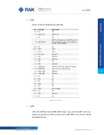
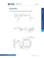
2.6
Micro-B USB Interface
A Standard Micro-B USB compliant with USB 2.0 standard specification is used to
provide an interface to connect to a PC for control of the board and firmware upgrade.
The Micro-B USB pin definition is shown below:
Pin
Description
1
USB_VBUS (+5V)
2
USB_DM
3
USB_DP
4
NC
5
GND
Table 3
| Micro-B USB Pin Descriptions
2.7
LEDs
Three LEDs are used to indicate operating status, here are their functions:
Green LED:
STATUS
– Defined by user.
Blue LED:
STATUS
– Defined by user.
Red LED:
Charging Status
– indicates the Li-ion Battery is charging.
2.8
RESET Push Button
Reset Push Button is used to reset the RAK811 module. To reset the module push the
Reset Button for 1 second.
2.9
Working Mode
The board supports to enable the GPS low power mode, it has a 3-axis MEMS Sensor
LIS3DH, which can detect the user's motion status, when the device is stationary, it will
enter the low power sleep mode, reducing the overall power consumption and increase
battery life. The power consumption as shown in the following table.
Mode
Power consumption
Sleep mode
14.5μA (Min)
Normal mode
174mA (Max) @ 20dBm and GPS enable
Table 4
| Power consumption
M
ic
ro
-B
U
S
B
In
te
rfa
ce