


www.raisecom.com
User Manual
7
Chapter 4
Device Settings
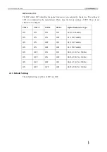
4.1 DIP switch description
4.1.1 The location of the DIP switches
There are an 8-bit DIP switch SW1 and a 4-bit DIP switch SW2 on the back of the print circuit
board.
4.1.2 DIP switch description
DIP switch SW1
¾
Bit 1~3
: Reserved
¾
Bit 4
: ALS function setting
Bit 4
ALS function setting
OFF Disable
ON Enable
¾
Bit 5
: E1 loopback setting
Bit 5
E1 loopback setting
OFF No
loopback
ON Loopback
¾
Bit 6
: Reserved
¾
Bit 7
: Loopback type setting
Users can set the loopback of E1 to “remote bidirectional loopback” or “local bidirectional
loopback” when the loopback of the E1 is enabled.
The following two figures show the loopback point of the remote bidirectional loopback and
local bidirectional loopback respectively.
Bit 7
Loopback type selection
OFF
Remote bidirectional loopback
ON Local
bidirectional
loopback


