WWW.RAISE3D.COM
AMERICA · ASIA · EUROPE
Filament Run-out Sensor Installation Guide
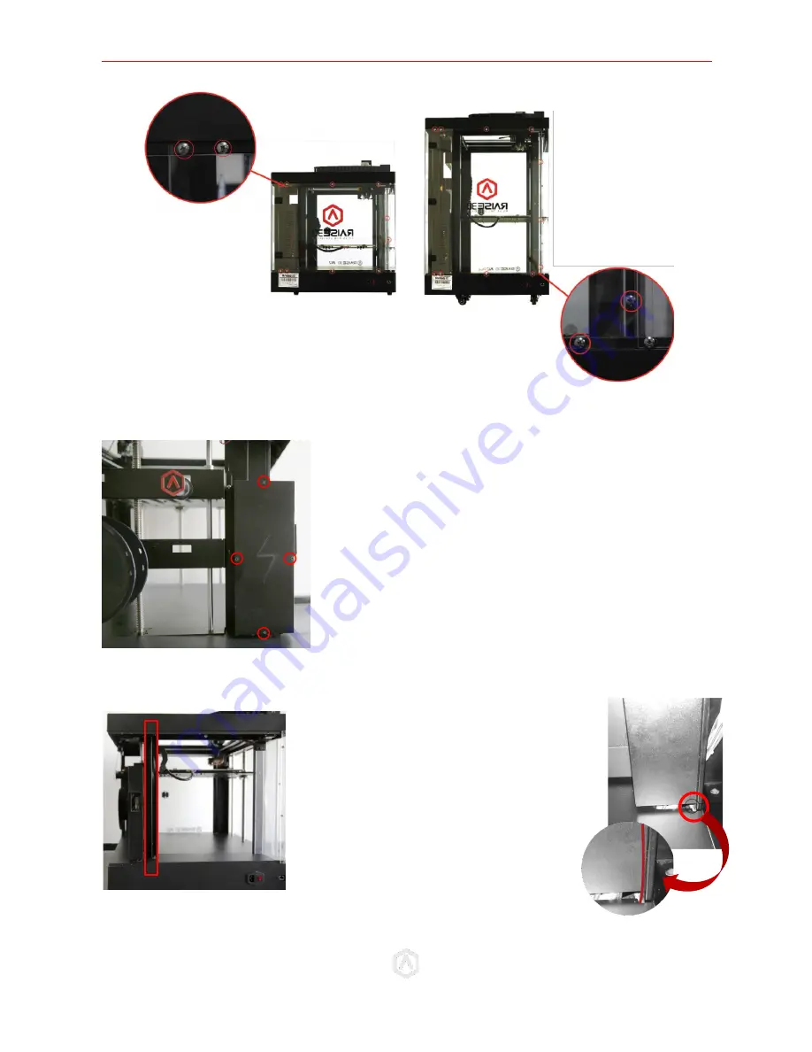
STEP 3: Open the electronic box cover
STEP 4: Remove the Wires Path Covering
STEP 5: Wiring
N2: 10 screws
N2 Plus: 11 screws
If your printer model has a covering
for the wire-path behind the electrical
box, remove this covering. (See Left)
If there is no removable cover on the
wiring guide tube of your printer,
please inset the end of the cable into
the gap between guide tube and
bottom cover. Then drag it into the
electronic box. (See Right)
Remove the 4 fixing screws with a 2mm hex wrench.
If your model does not have visible screws, this cover
may be removed by utilizing the push tabs that
connect the cover to the frame.


