background image

Page 7

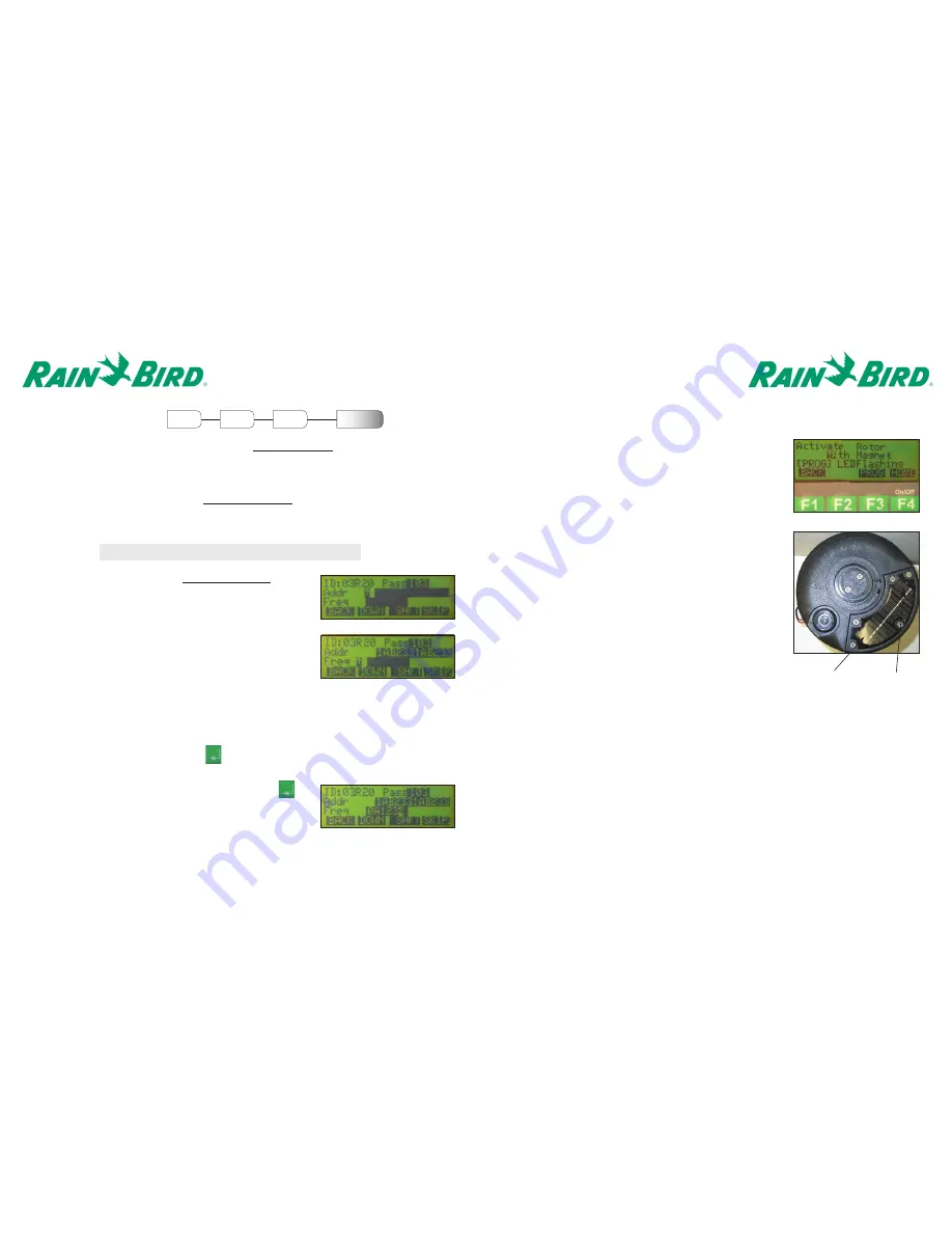
5. The Handheld is now ready to configure the Rotor.

Once the “Activate Rotor With Magnet” screen
appears, activate the rotor by passing a magnet
across the LED display area of the 
Solar Panel. The magnet should pass over the LED
once with the surface of the magnet slightly
brushing along the top of the solar panel.

Observe the flashing of the LED on the Solar Panel.
Once the LED begins to flash approximately once 
every second, press the Prog <F3> key on the
Handheld.

After approximately 30 seconds, the solenoid should
click twice to indicate that the Rotor has been
successfully configured.

6. By default, the handheld will prompt for the next

Rotor ID to be configured. To enter another Rotor ID,
return to step 1 of this section. If finished, press the
Home <F4> to return to the main menu.

Page 6

CONFIGURING A ROTOR   

Prior to being able to perform any of the functions for 

Controlling a Rotor,

the Rotor configuration

data must be input into the Handheld and then transferred into the Rotor with the use of a magnet.
The configuration data for the Wireless Rotor requires that the Capcode and Frequency be converted
into hexadecimal code. Rain Bird will supply the converted codes. In addition to assigning a logical
address to each Rotor as discussed in the 

Entering the Rotor ID

section, a unique PassCode must

also be assigned. This three-digit numerical code allows each rotor to determine whether or not a
particular command from the Central Control Software or Handheld pertains to itself.

F1

F2

Enter

Rotor ID

Enter Config

Data

MAIN

MENU

Menu

Conf

1. Enter the Rotor ID as shown in the 

Entering the Rotor ID

section.

2. At the Configuration Data Screen, begin by entering the

PassCode using the keypad. After entering the third digit, the
cursor will automatically move to the Address line.

3. Enter the Address information provided by Rain Bird. After 

the last character has been entered, the cursor will automatically
move to the Frequency line.

4. Enter the Frequency information provided by Rain Bird.

After the last character has been entered, press <enter>
on the keypad. Remember to use the Shft <F3>
followed by the number 1-6 to enter A-F.

Note: It is best to configure the rotor prior to installation

Some addresses and frequencies contain the characters A-F. To enter one of  these characters,
press the Shft <F3> followed by the number 1-6, where 1 represents A and 6 represents F.

If other Rotors have been previously programmed into the Handheld, you can  scroll through each
address by continuously pressing the Down <F2> key until the correct address is found. Once the
correct address is found, press <enter>        on the keypad.

Solar Panel

LED

Summary of Contents for EAGLE 500 series

Page 1: ...rmful interference and 2 This device must accept any interference received including interference that may cause undesired operation The term IC before the certification registration number only signi...

Page 2: ...NTENTS Description Page Introduction 2 Maintenance 3 Wireless Handheld 4 Configure Key Function 6 Control Key Functions 8 Unit Key Functions 11 Rain Bird Messenger 13 Listening Device 17 Station Detai...

Page 3: ...n this product including the Rain Bird standard top serviceable features For performance data and maintenance information please refer to the EAGLE Series Rotor catalog Special screws have been used t...

Page 4: ...the unit will be shut off automatically Additionally the backlight feature of the LCD Display screen will only remain active for 10 minutes After 10 minutes the LCD Display screen will return to its n...

Page 5: ...address to each Rotor as discussed in the Entering the Rotor ID section a unique PassCode must also be assigned This three digit numerical code allows each rotor to determine whether or not a particul...

Page 6: ...ress 2 on the keypad and enter a duration The duration is a three digit value representing the number of minutes to irrigate 240 minute maximum For example 005 represents 5 minutes Press enter on the...

Page 7: ...user must provide the appropriate three digit Security Password Alternatively a magnet can be used to reactivate the Rotor for operation without the use of the Handheld By selecting 4 Reset the Rotor...

Page 8: ...Setup exe 5 The following three screen shots will open Please click the Next button on each screen Page 12 Clear Rotor Database Within the Clear Rotor Database menu the user must verify whether or no...

Page 9: ...r Rain Bird Messenger If you do not have MicroSoft 2 5 Data Components on your hard drive then they will also be installed at this time 7 The first few set up screens indicate the amount of time it wi...

Page 10: ...under the wireless rotor symbol Always use the 2nd row down when setting up the wireless rotor See picture on page 18 Page 16 12 Click on the drop down arrow and select the Pager Service to be used Cl...

Page 11: ...king the box as indicated in Step 2 the following screen will appear Check in the Listening Device Present box to complete the setup of the listening device With the Listening Device unit active the C...

Page 12: ...on is input as shown on page 14 Programming the Wireless Rotor To create irrigation programs using the Cirrus NimbusII StratusII Central Control software please refer to the operations manual for the...

Reviews: