


w w w . R A I D O N . c o m . t w
Your Data Security Guardian
Step 6
Connect the AC power cable to the GR5630-WSB3+, and then plug the AC power to the
wall socket. Boot-up the unit.
Step 7
Set the storage mode using the LCD and buttons on the front (please refer to section 5 for
front panel and LCD information).
Step 8
Connect the cable to the PC and the GR5630-WSB3+ port.
Step 9
After boot-up, your operating system will automatically detect the storage capacity of your
hard drives. Please follow the operating system instructions to configure and format your
drives. The formatted drives can be configured for the RAID setup.
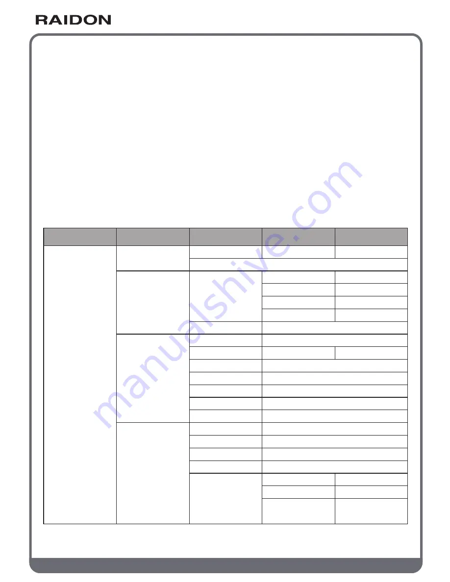
Chapter 5 Description of Front Panel Operation
and LCD Information
Level 0
External 4BAY
HARDWARE
RAID
Quick Setup
Create One RAID
Delete All RAID
Identify Disk
Show Disk Info
Identify RAID
Create RAID
Delete RAID
RAID Info
Change RAID Pwd
Rebuilding Priority
Standby Timer
System Info
Changhe Password
Logout From Menu
Alarm Control
Voltage Monitor
< 3.3V / 5V / 12V >
< Temp. >
< Fan Speed /
Fan Level >
Temp. Monitor
Fan Monitor
Hardware Monitor
Select Disk
< Disk Info >
Select RAID
RAID 0 / RAID 5
Select RAID
< Password >
for RAID Setup
Highest/High/Medium/Low/Lowest
< 99999min >
Firmware Version
< Password >
for System Info
< Y or N >
Mute the Buzzer
Disk 1
Disk 2
Disk 3
Disk 4
Check Disk LED
Check Disk LED
Check Disk LED
Check Disk LED
RAID 0/ RAID 5
Select Disk
Disk Manager
RAID Manager
System Manager
Level 1
Level 2
Level 3
Level 4


