14
www.raider.bg
• The machine must be set up so that it stands firmly, i.e. it must be securely screwed to a
work bench or similar. • All covers and safety devices have to be properly fitted before the
equipment is switched on. • The grinding and polishing wheel must rotate freely. • Check that
the voltage on the rating plate is the same as your supply voltage before you connect the
equipment to the power supply.
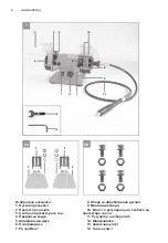
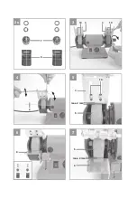
3.1 Fitting the spark refl ector (Fig. 2-4 / Item 3) Fit the spark refl ector (3) to the double
wheel grinder using the adjusting screw (10).
3.2 Adjusting the spark refl ector (Fig. 5 / Item 3) • Adjust the spark deflector (3) using the
adjusting screw (10) so that the distance between the dry grinding wheel (5) and the spark
deflector (3) is as small as possible and certainly does not exceed 2 mm. • Adjust the spark
deflector (3) periodically to compensate for wear on the wheel.
3.3 Fitting the workpiece supports (Fig. 6 / Item 8)
Secure the workpiece supports (8) to the double wheel grinder using the star screw (7).
3.4 Adjusting the workpiece supports (Fig. 7 / Item 8) • Adjust the workpiece supports (8)
using the star screws (7) so that the distance between the dry grinding wheel (5) and the
workpiece support (8) is as small as possible and certainly does not exceed 2 mm. • Adjust
the workpiece supports (8) periodically to compensate for wear on the dry grinding wheel (5).
3.5. Changing the wheels (Fig. 8-9)
Remove the 3 screws (A) holding the side section of the safety hood (B) and remove the
safety hood. Slacken the nut (D) (Important: The grinding wheel on the left is fastened with a
lefthanded thread and the grinding wheel on the right with a right-handed thread) by holding
the nut of the grinding wheel mount on the opposite side. Then remove the fl ange (C) and
replace the grinding wheel (5). To assemble, proceed in the reverse order. The grinding wheel
is mounted with the help of a rag. Mount the fl ange (C) and the nut (D) on the shaft and hold
steady with the help of a rag when you tighten the nut (D).
3.6 Installing the fl exible shaft (Fig. 10) • Insert the internal axle (a) of the flexible shaft (12)
into the guide shaft of the equipment. • Secure the fastening nut of the flexible shaft to the
equipment thread by hand (left-hand thread).
Important!
When you work with the fl exible shaft (12), the safety glass (2) must be placed right up
against the workpiece support (8) in order to prevent uncontrolled touching of the wheels.
3.7 Inserting the various tools into the fl exible shaft (Fig. 11)
1. Press the supplied locking pin (13) into the hole in the fl exible shaft (12) and turn the
shaft until the pin latches in place.
2. Now undo the collet chuck nut.
3. Insert the required tool into the sleeve as far as the stop and screw the collet chuck nut
tight.
4. Operation
4.1 On/Off switch (1)
To switch on the equipment set the On/Off switch (1) to position I.
Move the On/Off switch (1) to position 0 to switch off the equipment.
Important!
When you are not working with the fl exible shaft (12), it is not allowed to be mounted on
the equipment because it could then fl y around out of control.
After switching on, wait for the equipment to reach its maximum speed of rotation. Only
then should you begin with the grinding.
4.2. Speed selector (Fig. 1)
The required speed can be set with the speed control (11).
4.2.1 Speed of the fl exible shaft
The correct speed depends on the tool used and the type of material being processed.
4.3. Information on speed settings • Small cutters/grinding pins: High speed • Large cutters/
grinding pins: Low speed
4.4. Work practice • Exert only moderate pressure on the workpiece so that it can be
Summary of Contents for RD-BG06
Page 52: ...52 www raider bg Exploded drawing of Bench Grinder RD BG06 ...
Page 62: ...62 www raider bg ...
Page 67: ...67 ...


