16
www.raider.bg
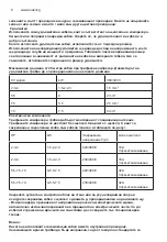
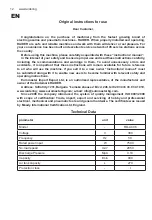
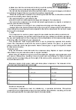
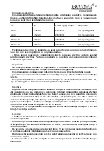
HP
kW
Power sypply volt/ph
Plug model
2-3-4
1.5-2.2-3
220/380/3
16A 3 pole+ground
2-3-4
1.5-2.2-3
230/400/3
16A 3 pole+ground
5.5-7.5-10
4-5.5-7.5
220/380/3
32A 3 pole+ground
5.5-7.5-10
4-5.5-7.5
230/400/3
32A 3 pole+ground
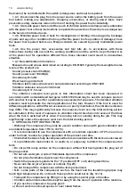
Secure the control box box to a wall or a fixed support and secure a power cord with a plug
that is proportional to its length.
- Any damage caused by incorrect connections to the mains automatically excludes the
warranty of the electrical parts. To avoid connection errors, we recommend that you contact
a specialist technician.
Important:
Never use a grounding cable in place of a neutral conductor. The earthing connection must be
made to meet safety standards.
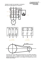
The compressors only thicken in one direction of rotation. The direction of rotation is not
problem with single-phase compressors as they always start and run in the right direction.
Three-phase compressors rotate in either direction depending on the supply phases - L1, L2
and L3. Please follow the instructions on the equipment.
Installation
After removing the compressor from its packaging and verifying that it is in excellent condition
and no damage has occurred during transportation, you must perform the following actions:
the instructions that are provided. Place the compressor on a flat surface or at a maximum
inclination of 10 ° in a well-ventilated place, protected from the weather and not in an explosive
atmosphere. If the surface is flat and smooth, make sure that the compressor will not move
when commissioned. For proper ventilation and efficient cooling, it is important that the
compressor is located at least 100 cm from the wall.
Make sure that the compressor is transported properly, do not turn it with its head down or lift
it with hooks or ropes.
Startup
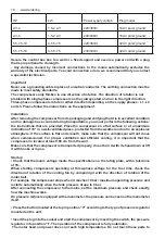
• Check that the mains voltage meets the specifications on the rating plate, with a tolerance
of 5%.
When starting compressors operating at three-phase voltage for the first time, check the
direction of rotation of the cooling fan by comparing it with the direction of rotation of the
motor belt.
For example, the compressor stops when it reaches 10 bar / maximum operating pressure and
restarts automatically when the tank pressure drops to 8 bar.
After connecting the compressor to the mains, set the maximum pressure and check exactly
how the machine works.
On pressure reducers equipped with a manometer, the pressure can be seen on the manometer
itself.
• Press the button located at the top in position “0” according to the type of pressure regulator
mounted on the unit.
• Insert the plug into the socket and start the compressor by inserting the switch, the pressure
regulator, into position “I”. The operation of the compressor is fully automatic.
The motor head and power lines can reach high temperatures. Do not touch these parts to
Summary of Contents for 089404
Page 7: ...7 2 5 C 40 C 70 0 OFF 3...
Page 9: ...9 L1 L2 L3 10 100 5 10 bar 8 0 I 4...
Page 10: ...10 www raider bg 0 0 5 C C2 B1 B2 0 C 6 7 8 50 1 2 5 35 SAE 5W50...
Page 11: ...11 9 2012 19...
Page 26: ...26 www raider bg...
Page 30: ...30 www raider bg 2 5 C 40 C 70 0 OFF No 3...
Page 32: ...32 www raider bg L1 L2 L3 10 100 5 10 bar 8 0 I 4...
Page 33: ...33 0 0 5 C C2 B1 B2 0 6 7 8 50 1 2...
Page 34: ...34 www raider bg 5 35 SAE 5W50 9 2012 19...
Page 50: ...50 www raider bg 2 5 C 40 C 70 0 OFF UIT 20 12 13 3...
Page 52: ...52 www raider bg 10 100 cm 5 10 bar 8 bar 0 I 4 0 0 5...
Page 53: ...53 C C2 B1 B2 0 C 6 7 8 50 1 2 5 35 SAE 5W50 9 2012 19 E...
Page 57: ...57 0 OFF 3...
Page 59: ...59 100 5 10 8 0 I 4 0 0 5 C C2 B1 B2...
Page 60: ...60 www raider bg 0 6 7 8 50 1 2 5 35 SAE 5W50 9 2012 19...
Page 68: ...68 www raider bg exploded view...
Page 69: ...69 spare parts list...
Page 74: ...74 www raider bg 246 0700 44 155...
Page 76: ...1 5 2 bar Raider 18 Raider Industrial Raider Pro 12 Raider Power Tools Raider Garden Tools...
Page 77: ...112 115 112 1 2 1 2 3 113 1 2 3 2 114 4 5 114 1 113 1 2 2 3 115 4 115 1 2 1 3 1 1...
Page 83: ...83...
Page 84: ...84 www raider bg 45...
Page 88: ...88 www raider bg...

