background image

RAE PowerPak User’s Guide 


27 


14 

 Troubleshooting & Repair 


The RAE PowerPak is designed to be trouble-free and require no 

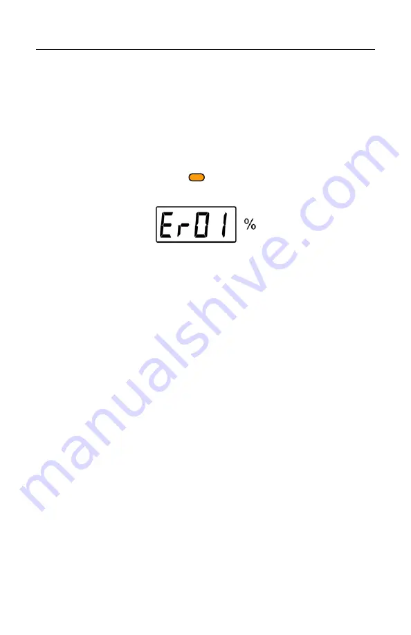
maintenance. However, if you see the status LED glow orange and 

an error message in the display, refer to the error message table on 

page 12 and take the suggested action. 


14.1  Encapsulated Internal Battery Replacement 


In the unlikely event that one of the encapsulated internal batteries 

needs replacement, it is easy to replace them in the RAE 

PowerPak. Follow these steps, and only replace an encapsulated 

internal battery with a RAE Systems model with the same part 

number (F03-3002-000). 


WARNING! 

Only open the RAE PowerPak enclosure and change or charge 

encapsulated internal batteries in a non-hazardous location or with 

a “hot zone” permit. 

Summary of Contents for FTB 1000

Page 1: ...Rev A July 2009 P N F03 4001 000 RAE PowerPak User s Guide...

Page 2: ...Copyright 2009 RAE Systems Inc Ordering Replacement Parts If you need replacement parts a list is available online http www raesystems com...

Page 3: ...5 Physical Description 10 6 LCD LED 11 7 LED Status Indicator 11 8 LCD Status Information Error Messages 12 9 Installation 14 10 Operation Instructions 17 11 Connection 18 12 Changing The RAE PowerPak...

Page 4: ...stitution of components may impair suitability for intrinsic safety Replace encapsulated internal batteries only in non hazardous locations Warning Charging of the FTB 1000 by means of mains charger c...

Page 5: ...rPak Type FTB1000 Serial No barcode F032XXXXXX IECEx DNV 09 0003X Ex ia I IIC T4 0575 IM1 II 1G Ex ia I IIC T4 DNV 09 ATEX 55726X Cl I Dv 1 Group A B C D T4 Only as to intrinsic safety for use in haza...

Page 6: ...ses of explosion groups A B C or D and temperature class T4 may be present 1 3 Instruction For Safe Use Strictly follow the instructions for safe use Application of the RAE PowerPak requires full unde...

Page 7: ...components may not be modified in any way The appropriate regulations for service and repair must be properly observed during such activities FCC Part 15 statement and CE This device complies with Par...

Page 8: ...Cable for connecting MeshGuard to RAE PowerPak D01 3003 000 3 General Information The RAE PowerPak FTB 1000 is an intrinsically safe rechargeable battery power source for use with a MeshGuard EC or Me...

Page 9: ...ays or MeshGuard Router 1 5 months Rugged stainless steel enclosure Very low cost installation no hardwiring involved Very little maintenance or monitoring Large easy to read continuous display of pow...

Page 10: ...Carrying handle 2 Stainless steel enclosure 3 Status LED 4 Status LCD 5 Protective bezel for connections 6 Power output port to MeshGuard 7 Power output dust cap 8 Power input from charger 9 Power in...

Page 11: ...or green depending on different status alerts it is conveying Color Indication Related LCD Message Green Battery or batteries fully charged LCD says FULL Red Battery or batteries charging LCD says CH...

Page 12: ...age too high Er09 Battery 1 temperature too low Er10 Battery 2 temperature too low Er11 Battery 3 temperature too low Er12 Battery 4 temperature too low Er13 Wrong battery type Er14 Wrong charger Er15...

Page 13: ...ced Contact RAE Systems service The number of batteries is indicated by the number of segments showing in the left side of the display These segments correspond to the battery locations the enclosure...

Page 14: ...urface Before attaching the steel plate to a surface you should attach the metal enclosure for the MeshGuard to the plate 1 Place the MeshGuard in the steel enclosure 2 Turn the plate and MeshGuard ov...

Page 15: ...e plate to a wall or other solid flat surface by using M8 size screws with flat washers and locking washers following this diagram At a minimum use four screws at the corners The MeshGuard has been re...

Page 16: ...has been fully charged before installation Use the latch to lock the RAE PowerPak in place Align the RAE PowerPak with the rails on the metal plate Slide the RAE PowerPak down until it stops Flip the...

Page 17: ...ack is only to be used with RAE Systems products whose entity parameters match the entity parameters of the RAE PowerPak Fig 1 Connections Fig 2 RAE PowerPak connected to the MeshGuard The RAE PowerPa...

Page 18: ...can replace the internal battery in the MeshGuard Use the sensor and battery removal tool as shown The connector from the RAE PowerPak screws into the MeshGuard s battery compartment Bottom views of t...

Page 19: ...on the power end tighten by turning clockwise until it is snug Do not overtighten On the bottom of the RAE PowerPak are two dust caps that are screwed onto the connectors Unscrew the one on the left b...

Page 20: ...RAE PowerPak User s Guide 20 Screw the end of the connecting cable to the port on the bottom of the RAE PowerPak Do not use tools or overtighten...

Page 21: ...RAE PowerPak User s Guide 21 12 Changing The RAE PowerPak 1 Unscrew the battery connector from the RAE PowerPak 2 Loosen the safety screw holding the battery latch...

Page 22: ...RAE PowerPak User s Guide 22 3 Raise the latch 4 Lift up the battery and slide it off the steel plate...

Page 23: ...RAE PowerPak User s Guide 23 5 Mount a fully charged RAE PowerPak on the mounting bracket 6 Flip the latch down 7 Tighten the safety screw...

Page 24: ...the RAE PowerPak and whenever the RAE PowerPak shows a low power reading 10 or less you should charge it in a safe location 1 If the RAE PowerPak is currently in service and is attached to a MeshGuard...

Page 25: ...ect the AC mains cord from the Charger to an AC power plug 4 The LED above the display should glow red and the display should say CHRG If not check your connections and the AC outlet 5 When the RAE Po...

Page 26: ...owerPak 8 Screw the cap back on over the charging port on the bottom of the RAE PowerPak 9 Place the RAE PowerPak on the steel mounting plate detailed instructions are shown on page 14 10 Follow the i...

Page 27: ...ed action 14 1 Encapsulated Internal Battery Replacement In the unlikely event that one of the encapsulated internal batteries needs replacement it is easy to replace them in the RAE PowerPak Follow t...

Page 28: ...RAE PowerPak User s Guide 28 1 Unscrew the four screws on the front of the enclosure 2 Disconnect the battery s power jumper from the main printed circuit board...

Page 29: ...RAE PowerPak User s Guide 29 3 Remove the screws at both ends of the battery These attach the bracket that holds the battery in place 4 Lift out the bracket and the battery...

Page 30: ...screws and tighten them with a screwdriver Before replacing the front cover check the display If it is not working then the ribbon cable between the display and the main circuit board might have beco...

Page 31: ...ontain one or more sealed lead acid nickel cadmium NiCd nickel metal hydride NiMH lithium Li or lithium ion batteries Specific battery information is given in this user guide Batteries must be recycle...

Page 32: ...m x 14 6 cm 14 25 H x 10 25 W x 5 75 D Weight 15 kg 33 lbs with four internal batteries Package IP 65 Output Voltage 3 3V 0 1V Maximum Output Current 0 33A Capacity Two internal battery units 26Ah Fou...

Page 33: ...tested in an explosive gas air atmosphere having an oxygen concentration greater than 21 Substitution of components may impair suitability for intrinsic safety Replace encapsulated internal batteries...

Page 34: ...ak Type FTB1000 Serial No barcode F032XXXXXX IECEx DNV 09 0003X Ex ia I IIC T4 0575 IM1 II 1G Ex ia I IIC T4 DNV 09 ATEX 55726X Cl I Dv 1 Group A B C D T4 Only as to intrinsic safety for use in hazard...

Page 35: ...ases of explosion groups A B C or D and temperature class T4 may be present Instruction For Safe Use Strictly follow the instructions for safe use Application of the RAE PowerPak requires full underst...

Page 36: ...xplosive atmospheres and which has been assessed and certified according to international regulations may be used only under specified conditions The components may not be modified in any way The appr...

Page 37: ...RAE Systems by Honeywell World Headquarters 3775 N First St San Jose CA 95134 1708 USA Phone 408 952 8200 Toll Free 888 723 4800 Fax 408 952 8480 Rev A July 2009 P N F03 4001 000...

Reviews: