


Electrical Interfaces
DMD2401/DMD2401L/DMD2401 IBS/IDR Satellite Modem
5-34
TM065 – Rev. 3.3
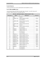
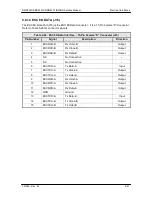
Table 5-32. Asynchronous Interface - 9-Pin Female “D” Connector (J17)
Pin Number
Signal
Description
Direction
1
TX-485-B
Transmit Data RS485 (+)
Input
2
TXD-232
Transmit Data RS232
Input
3
RXD-232
Receive Data RS232
Output
5
GND
Ground
–
4
NC
Not Connected
–
9
RX-485-A
Receive Data 485 (-)
Output
8
RX-485-B/CTS
Receive Data 485 (+)
Output
6
TX-485-A
Transmit Data 485 (-)
Input
7
RTS
Request to Send
Input
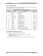
5.9 Async Port Configuration Switches
The switch settings listed below in Tables 5-33 through 5-37 are used to configure the Async Port
for the following applications. The DIP Switches are located on the inside of the unit on the Async
Card with the exception of the AS/3771 Daughter Card and the AS/4803 Universal Daughter Card
(discussed below). The user must remove the top cover of the unit to access these switches.
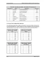
Table 5-33. Async Port DIP
Switch Settings – RS-485
Only
Table 5-34. Async Port DIP
Switch Settings – RS-232 or
RS-485
1
OFF
1
ON
2
OFF
2
ON
3
OFF
3
OFF
4
OFF
4
OFF
5
OFF
5
OFF
6
ON
6
ON
Table 5-35. Async Port DIP
Switch Settings – RS-232
Only with CTS & RTS
Table 5-36. Async Port DIP
Switch Settings – RS-232
Null or RS-485
1
ON
1
OFF
2
ON
2
OFF
3
OFF
3
ON
4
OFF
4
ON
5
ON
5
OFF
6
OFF
6
ON
Summary of Contents for DMD2401 IBS
Page 2: ......
Page 15: ......
Page 60: ...DMD2401 DMD2401L DMD2401 IBS IDR Satellite Modem User Interfaces TM065 Rev 3 3 4 21...