background image


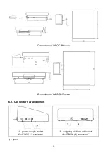
Dimensions of WLC/C2/K scale 


Dimensions of WLC/C2/R scale 


6.2. Connectors Arrangement 


– power supply socket 

– RS232 (1) connector 

– weighing platform cable inlet 

– RS232 (2) connector * 


*)


– option. 

Summary of Contents for WLC

Page 1: ......

Page 2: ...2 APRIL 2021...

Page 3: ...dusty environments In case of damage immediately unplug the device from the mains Scales to be decommissioned must be decommissioned in accordance with valid legal regulations Do not let battery disch...

Page 4: ...7 5 RECYCLING 8 6 MECHANICAL DESIGN 8 6 1 Dimensions 8 6 2 Connectors Arrangement 9 6 3 Pins Overview 10 6 4 Operation panel 10 7 INSTALLATION 11 7 1 Unpacking and Installation 11 7 2 Levelling 11 7 3...

Page 5: ...om unauthorized or inadequate performing of production or service processes D The warranty does not cover mechanical damage caused by product exploitation other than intended damage of thermal and che...

Page 6: ...lic solvent sodium carbonate to remove BASE use protogenic solvent mineral acid of various concentration In case of heavy contamination use brush and detergent nevertheless avoid detergents containing...

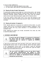
Page 7: ...brasive substances Avoid using hard brush this may cause scratches It is recommended to use microfibre cloth While polishing the surface use circular movements Use clean dry cloth to make the surface...

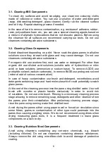
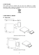
Page 8: ...they are not to be treated as a regular household waste Scales to be decommissioned must be decommissioned in accordance with valid legal regulations 6 MECHANICAL DESIGN 6 1 Dimensions Dimensions of W...

Page 9: ...9 Dimensions of WLC C2 K scale Dimensions of WLC C2 R scale 6 2 Connectors Arrangement 1 power supply socket 2 RS232 1 connector 3 weighing platform cable inlet 4 RS232 2 connector option...

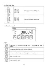
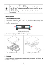
Page 10: ...D Pin4 5VDC Pin5 GND RS232 2 connector DB9 M male 6 4 Operation panel Keys Press to switch the weighing device on off hold the key for about 1 second Function key press to change the working mode Pres...

Page 11: ...g and Installation Unpack the device and place it on a flat and even surface Keep it far away from any sources of heat Remove transport lock WLC F1 WLC C2 Scales Install the weighing pan follow the be...

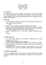
Page 12: ...ext displayed reading unit is conditioned by scale type In case the weighing result is not zero after indication stabilisation press key 7 4 Warm Up Time For correct scale operation the workroom tempe...

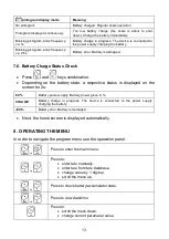
Page 13: ...nation Depending on the battery state a respective status is displayed on the screen for 2s 80 Battery power supply Battery power given in CHArGE Battery charge in progress The device is connected to...

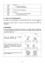
Page 14: ...ome screen To return to the home screen press key repeatedly 9 WEIGHING Load the weighing pan Read the result when stability marker is displayed To assure long term operation and correct mass measurem...

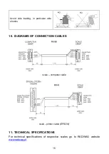
Page 15: ...g in particular side shocks 10 DIAGRAMS OF CONNECTION CABLES scale computer cable scale printer cable EPSON 11 TECHNICAL SPECIFICATIONS For technical specifications of respective scales go to RADWAG w...

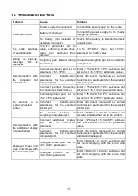
Page 16: ...transmission Enter P5 ducE 5 1 PC submenu and set correct 5 1 3 Int parameter value No printout on a scale connected printer Incorrect printer port set in 5 2 1 Prt parameter Enter P5 ducE 5 2 Prtr s...

Page 17: ...art mass error indication out of range 10 of start mass H i Display range of total mass on scale display exceeded in Totalizing mode u L o Too low battery charge The scale is about to shut down E r r...

Page 18: ...18...

Reviews: