RADSON Vido Series Installation, Operating, Maintenance & After Sales Manual Download Page 39

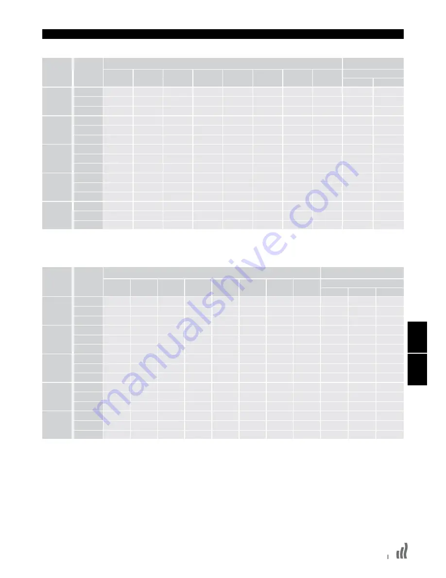
11.0  Données techniques

Puissance 2 tubes

Humidité relative: refroidissement sensible à 50%

Model

Débit 

(l/h)

T20

T25

T30

T35

T40

T45

T50

Puissance calorifique (Watt)

Puissance frigorifique (Watt)

Condition  7-12-27

Vitesse de 

ventilation

  Normal 

341 

738 

940 

1146 

1355 

1567 

1781 

1997

  Medium 

341 

989 

1260 

1537 

1817 

2101 

2388 

2678 

  Boost 

341 

1360 

1733 

2113 

2499 

2889 

3284 

3682 

  Normal 

450 

1012 

1289 

1572 

1859 

2149 

2443 

2739 

  Medium 

450 

1352 

1723 

2101 

2484 

2872 

3265 

3661 

  Boost 

450 

1892 

2412 

2941 

3477 

4020 

4569 

5124

  Normal 

600 

1214 

1548 

1887 

2231 

2580 

2932 

3288 

  Medium 

600 

1643 

2094 

2553 

3018 

3490 

3967 

4448 

  Boost 

600 

2409 

3070 

3743 

4425 

5117 

5815 

6521

  Normal 

700 

1428 

1820 

2219 

2624 

3034 

3449 

3867

  Medium 

700 

1945 

2478 

3022 

3573 

4131 

4695 

5265

  Boost 

700 

2916 

3716 

4531 

5357 

6194 

7040 

7894

  Normal 

800 

1647 

2099 

2560 

3027 

3499 

3977 

4460

  Medium 

800 

2246 

2863 

3491 

4127 

4772 

5424 

6082 

  Boost 

800 

3422 

4362 

5318 

6288 

7270 

8263 

9266

600x800

600x1000

600x1200

600x1400

600x1600

Total

Sensible


707 

527

  1126 

829

  1648 

1227

  1011 

753

  1600 

1178

  2304 

1716

  1520 

931

  1960 

1442

  2918 

2173

  1490 

1110

  2320 

1707

  3533 

2631

  1729 

1288

  2679 

1972

  4147 

3088

Pour BTU multiplier Watt par 3,412

Puissance 4 tubes

Humidité relative: refroidissement sensible à 50%

Model

Débit 

(l/h)

T20

T25

T30

T35

T40

T45

T50

Puissance calorifique (Watt)

Puissance frigorifique (Watt)

Condition  7-12-27

  Normal 

300 

517 

658 

802 

949 

1097 

1247 

1398

  Medium 

300 

692 

882 

1076 

1272 

1471 

1672 

1875

  Boost 

300 

952 

1213 

1479 

1749 

2022 

2299 

2577

  Normal 

350 

708 

902 

1100 

1301 

1504 

1710 

1917

  Medium 

350 

946 

1206 

1471 

1739 

2010 

2286 

2563

  Boost 

350 

1324 

1688 

2059 

2334 

2814 

3198 

3587

  Normal 

400 

850 

1084 

1321 

1562 

1806 

2052 

2302

  Medium 

400 

1150 

1466 

1787 

2113 

2443 

2777 

3114

  Boost 

400 

1686 

2149 

2620 

3098 

3582 

4071 

4565

  Normal 

450 

1000 

1274 

1553 

1837 

2124 

2414 

2707

  Medium 

450 

1362 

1735 

2115 

2501 

2892 

3287 

3686

  Boost 

450 

2041 

2601 

3172 

3750 

4336 

4928 

5526

  Normal 

500 

1153 

1469 

1792 

2119 

2449 

2784 

3122

  Medium 

500 

1572 

2004 

2444 

2889 

3340 

3797 

4257

  Boost 

500 

2395 

3053 

3723 

4402 

5089 

5784 

6486

600x800

600x1000

600x1200

600x1400

600x1600

Total

Débit (l/h)

Sensible


350 

672 

501


350 

1070 

788


350 

1566 

1166


450 

960 

715


450 

1520 

1119


450 

2189 

1630


600 

1444 

884


600 

1862 

1370


600 

2772 

2064


700 

1416 

1055


700 

2204 

1622


700 

3356 

2499


800 

1643 

1224


800 

2545 

1873


800 

3940 

2934

Pour BTU multiplier Watt par 3,412

15

10.0

11.0

Vitesse de 

ventilation

Summary of Contents for Vido Series

Page 1: ...mber 1370071 Product Serial Number VIDO HEATING COOLING INSTALLATION OPERATING MAINTENANCE AFTER SALES MANUAL VIDO CHAUFFER REFROIDIR Manuel d installation d utilisation et de service VIDO VERWARMEN K...

Page 2: ...on 07 9 0 Electrical Connection 10 10 0 Commissioning Procedure 14 11 0 Technical Data 15 12 0 Control System Set up and Operating Instruction 17 12 1 Unit Operation 17 12 2 Operating Modes 19 12 3 In...

Page 3: ...correct installation of this unit it is essential that fixing is carried out in such a way that it is suitable for intended use and predictable misuse A number of elements need to be taken into consid...

Page 4: ...ote It is also possible to electronically remove the highest fan speed from the functionality of this unit via the control system see page 20 This may be advantageous on low temperature systems to pre...

Page 5: ...ter casing 3 Warranty card 4 Instruction manual 5 Fixing kit Check contents for concealed shipping damage Tools required Manual Warranty Grill Grill hinge Outer casing Filter Side cover Control panel...

Page 6: ...06 7 0 Fixing 236 457 B 236 457 NOTE Do not replace outer cover until connection to system and connection to electrical supply has been completed 1 2 3 4 5 6 Dimensions mm Dimensions mm...

Page 7: ...ted to avoid the condensate collector Connection to the heat exchanger should be made using straight connectors so that the pipework can more easily be routed past the condensate collector Pipe Routin...

Page 8: ...08 Dimensions 2 pipe 60 h 150 COOL OUT HOT OUT HOT IN COOL IN 153 595 523 99 69 29 31 477 380 304 95 141 125 Dimensions 4 pipe 8 0 Water Connection continued Dimensions mm Dimensions mm...

Page 9: ...require provision for condensate disposal in accordance with any local regulations A drain tray is fitted for condensate collection within the unit This should be connected to a 15mm drain pipe Altern...

Page 10: ...on all poles must be provided in an easily accessible position adjacent to the unit l Electrical cable entry to the unit should be made through the underside of the unit into the control box on the ri...

Page 11: ...ow and on page 12 13 After making the electrical connections replace the side cover to the control box 3 Routing cable TRANSFORMER L N Supply 230V 50Hz FAN POWER BOARD CONTROL BOARD WATER SENSOR 2 PIP...

Page 12: ...TER SENSOR 2 PIPE AIR SENSOR Input 230V 50Hz 24V DC 24V 50Hz COM FAST SLOW COOL HEAT BUILDING MANAGEMENT SYSTEM Lo Med Hi BL Y W R BR 24V AC 0 6A Max R W Y M T T M 2 pipe 1 valve BMS Voltage free cont...

Page 13: ...0Hz 24V 50Hz 24V DC R W Y M T T M Lo Med Hi BL Y W R BR HOT COLD 24V AC 0 6A Max BUILDING MANAGEMENT SYSTEM HEAT COOL SLOW FAST COM WATER SENSOR 2 PIPE AIR SENSOR WATER SENSOR 4 PIPE COOLING ONLY 4 pi...

Page 14: ...ions 2 l Refit the outer casing and secure with the 2 screws l Switch on the electrical supply l Check the operation of the unit by following the operating instructions 3 l Set up the installation par...

Page 15: ...3533 2631 1729 1288 2679 1972 4147 3088 For BTUs multiply Watts by 3 412 Performance Data 4 Pipe Relative Humidity Sensible cooling at 50 Model Flow l h T20 T25 T30 T35 T40 T45 T50 Heat Output Watts...

Page 16: ...t 202 302 403 504 605 Air Flow m3 h Condition 600x800 600x1000 600x1200 600x1400 600x1600 Fan Speed 11 0 Technical Data continued Model Dimensions Model Nominal Height mm Depth mm Length mm 600x800 60...

Page 17: ...t Full Mode Use and keys to select operating mode Refer to section 12 2 for details Setup parameters Refer to section 12 3 for details Full Mode Select Clock and set time Select Comfort setting Set ro...

Page 18: ...play The full control display can be accessed by pressing the and buttons for 5 seconds This action can be repeated to revert back to Easy Mode 1 Heating indicator 2 Cooling indicator 3 Temperature sy...

Page 19: ...l run according to one of the 9 preset timed programs or one of the 4 user defined programs See section 12 5 for program options and setup Press OK to view the actual set temperature Comfort or Set ba...

Page 20: ...in this mode If the BMS inputs are wrong e g P1 P2 or P3 P4 a message ERR BMS will flash and the system stops BMS control Parameter Name Default Setting Description Alternative Setting Select tempera...

Page 21: ...number Shows the daily program Use to see the other days in the program Built in programs description P1 Morning Evening Weekend P2 Morning Afternoon Evening Weekend P3 Day Weekend P4 Evening Weekend...

Page 22: ...ct AUTO setting in the user menu then press Down for 5 seconds Use the left and right arrows to scroll through the inputs outputs from relays air sensor water sensors BMS inputs and screen to check as...

Page 23: ...e the FILT display press and hold UP for 5 seconds Filters can be easily removed for cleaning as shown below See spare parts list section if replacement filters are needed Remove the old filter Place...

Page 24: ...All 6 Control Board 2 Pipe 4 Pipe 7 Transformer All 8 Motor 600x800 600x1000 600x1200 600x1400 600x1600 9 Filter 600x800 600x1000 600x1200 600x1400 600x1600 10 Secondary Condensate Tray All 11 Impell...

Page 25: ...FR VIDO CHAUFFER REFROIDIR Manuel d installation d utilisation et de service...

Page 26: ...hydraulique 07 9 0 Raccordement lectrique 10 10 0 Mise en service 14 11 0 Donn es techniques 15 12 0 R glage commande et fonctions 17 12 1 Fonctionnement 17 12 2 Modes de fonctionnement 19 12 3 Param...

Page 27: ...manuel ou par n gligence pendant l installation de l appareil et ses accessoires l Pour une installation parfaite des appareils il est primordial que la fixation de l appareil soit effectu e de mani...

Page 28: ...les pertes de chaleur calcul es dans l espace lorsque l unit tourne la vitesse normale soient compens es Les vitesses de ventilation plus lev es sont utilis es en mode Confort quand la temp rature am...

Page 29: ...anteau 3 Carte de garantie 4 Manuel d utilisation 5 Kit de fixation Contr lez le contenu pour voir s il n y a pas de dommages de transport cach s Outils n cessaires Manual Warranty Grille Charni re gr...

Page 30: ...06 7 0 Montage 236 457 B 236 457 NOTE Avant de remonter le manteau effectuer tous les raccordements hydrauliques et lectriques 1 2 3 4 5 6 Dimensions mm Dimensions mm...

Page 31: ...attention ce que les conduites ne touchent pas le bac de r cup ration du condensat Le raccordement l changeur de chaleur se fait avec des connecteurs droits de sorte que la tuyauterie puisse tre guid...

Page 32: ...08 Dimensions 2 tubes 60 K Dimensions 4 tubes 8 0 Raccordement hydraulique suite Dimensions mm Dimensions mm uit In SORTIE FROID SORTIE CHALEUR ENTR E CHALEUR ENTR E FROID...

Page 33: ...ent un dispositif d vacuation des eaux de condensation conform ment aux r glementations locales en vigueur L appareil a t quip d un bac de r cup ration du condensat Connectez le un tuyau d vacuation 1...

Page 34: ...place d acc s facile c t de l appareil La distance de s paration des contacts doit tre d au moins 3mm l Introduisez les c bles lectriques par le bas de l appareil via le presse toupe ajout jusqu au ta...

Page 35: ...e du tableau de commande 3 C blage TRANSFORMER L N Supply 230V 50Hz FAN POWER BOARD CONTROL BOARD WATER SENSOR 2 PIPE AIR SENSOR R W Y M T T M Lo Med Hi BL Y W R BR 2 tubes 0 vannes 9 0 Connexion GTB...

Page 36: ...y needed accross CO and COM to energise actuator Si vous utilisez nos vannes veuillez consulter les instructions ajout es au kit Contacts libres de potentiel alimentation 230V 50Hz n cessaire sur CO e...

Page 37: ...0Hz supply needed accross CO and COM to energise actuator Voltage free contacts 230V 50Hz supply needed accross CO and COM to energise actuator 9 0 Contacts libres de potentiel alimentation 230V 50Hz...

Page 38: ...ubes pour voir s il reste des fuites 2 l Replacer et fixer le manteau l aide des 2 vis l Mettre sous tension l Contr ler le fonctionnement de l unit suivant les diff rents pas du pr sent manuel 3 l R...

Page 39: ...3533 2631 1729 1288 2679 1972 4147 3088 Pour BTU multiplier Watt par 3 412 Puissance 4 tubes Humidit relative refroidissement sensible 50 Model D bit l h T20 T25 T30 T35 T40 T45 T50 Puissance calorifi...

Page 40: ...02 302 403 504 605 D bit d air m3 h Conditions 600x800 600x1000 600x1200 600x1400 600x1600 Vitesse de ventilation 11 0 Donn es techniques suite Mod le Dimensions Mod le Hauteur nominale mm Profondeur...

Page 41: ...section 12 3 pour plus de d tails Full Mode S lectionnez la fonction horloge et r glez l heure S lectionnez le mode confort R glez la temp rature ambiante souhait e par d faut 21 C Le ventilateur tou...

Page 42: ...ichage Full Mode En enfon ant les touches et pendant 5 secondes vous acc dez l cran du Full Mode Idem pour retourner au Easy mode 1 Indicateur chauffage 2 Indicateur refroidissement 3 Temp rature si c...

Page 43: ...t au mode chauffage est de 21 C Mode Auto L unit fonctionne suivant un des 9 programmes pr r gl s ou un des 4 programmes personnels de l utilisateur Voir section 12 5 pour options et r glage des progr...

Page 44: ...1 P2 ou P3 P4 le message ERRBMS clignote et le GTB arr te le pilotage du syst me D nomination Param tre R glage par d faut Description R glage alternatif S lectionner l chelle thermom trique dEG C F S...

Page 45: ...lisez les touches de navigation pour regarder les autres jours du programme P1 P1 Matin Soir Weekend P2 Matin Apr s midi Soir Weekend P3 Jour Weekend P4 Soir Weekend P5 Matin Soir Salle de bains P6 Ma...

Page 46: ...uche Down Utilisez les touches de navigation pour d filer les entr es sorties des relais sonde air sondes eau entr es GTB et cran pour contr ler Note Si pendant 1 minute aucune touche n est appuy e la...

Page 47: ...de sortir le filtre de l appareil pour le nettoyage voir dessin ci dessous S il vous faut des filtres nouveaux veuillez consulter la liste des pi ces d tach es Sortir le filtre Replacer le filtre 15...

Page 48: ...r Pas disponible comme pi ce d tach e 5 Tableau lectrique Tous 6 Tableau de commande 2 tubes 4 tubes 7 Transformateur Tous 8 Moteur 600x800 600x1000 600x1200 600x1400 600x1600 9 Filter 600x800 600x100...

Page 49: ...NL VIDO VERWARMEN KOELEN Installatie gebruikers en servicehandleiding...

Page 50: ...he aansluiting 07 9 0 Elektrische aansluiting 10 10 0 Inbedrijfstelling 14 11 0 Technische gegevens 15 12 0 Instelling bediening en functies 17 12 1 Werking 17 12 2 Functies 19 12 3 Parameterinstellin...

Page 51: ...n de toebehoren l Het is van essentieel belang dat de montage van het toestel zodanig gebeurt dat de installatie geschikt is voor het beoogde gebruik en voor voorspelbaar misbruik Hierbij moet voordat...

Page 52: ...warmteverliezen van de ruimte wanneer de unit aan de normale ventilatorsnelheid draait gecompenseerd worden De hogere ventilatorsnelheden worden gebruikt in de Comfortmodus wanneer de ruimtetemperatuu...

Page 53: ...assis 2 Mantel 3 Garantiekaart 4 Gebruiksaanwijzing 5 Bevestigingskit Controleer de inhoud op verborgen transportbeschadigingen Benodigd gereedschap Manual Warranty Rooster Roosterscharnier Mantel Fil...

Page 54: ...06 7 0 Montage 236 457 B 236 457 NOOT Sluit het toestel eerst hydraulisch en elektrisch aan vooraleer u de mantel terugplaatst 1 2 3 4 5 6 Afmetingen mm Afmetingen mm...

Page 55: ...jker verlopen Als u ook gaat koelen met het toestel moet u ervoor zorgen dat de leidingen de condensopvangbak niet raken Aansluiting op de warmtewisselaar moet met een rechte aansluiting gemaakt worde...

Page 56: ...08 Afmetingen 2 pijps 60 K Afmetingen 4 pijps 8 0 Hydraulische aansluiting vervolg Afmetingen mm Afmetingen mm uit In KOUDE UIT WARMTE UIT WARMTE IN KOUDE IN...

Page 57: ...oet het condenswater afgevoerd worden overeenkomstig de lokaal geldende reglementeringen Het toestel is binnenin uitgerust met een lekbak voor opvang van het condenswater Deze moet aangesloten worden...

Page 58: ...eidingsschakelaar te voorzien met een zekering van maximaal 3A De afstand tussen de contacten moet minstens 3 mm bedragen l De elektrische kabels moeten langs de onderkant van het toestel binnengebrac...

Page 59: ...ningspaneel terug 3 Kabelloop TRANSFORMER L N Supply 230V 50Hz FAN POWER BOARD CONTROL BOARD WATER SENSOR 2 PIPE AIR SENSOR R W Y M T T M Lo Med Hi BL Y W R BR 2 pijps 0 afsluiters 9 0 Aansluiting GBS...

Page 60: ...uator Voltage free contacts 230V 50Hz supply needed accross CO and COM to energise actuator Wanneer u de afsluiter gebruikt gelieve dan de bij de kit geleverde instructies te raadplegen Spanningsvrije...

Page 61: ...geleverde instructies te raadplegen Voltage free contacts 230V 50Hz supply needed accross CO and COM to energise actuator Voltage free contacts 230V 50Hz supply needed accross CO and COM to energise a...

Page 62: ...ingen op lekken 2 l Plaats de mantel terug en maak vast met de 2 schroeven l Schakel de stroomtoevoer aan l Controleer de werking van de unit volgens de stappen in de handleiding 3 l Stel de benodigde...

Page 63: ...631 1729 1288 2679 1972 4147 3088 Voor BTU Watt vermenigvuldigen met 3 412 Vermogen 4 pijps Relatieve vochtigheid voelbare koeling bij 50 Model Debiet l u T20 T25 T30 T35 T40 T45 T50 Verwarmingsvermog...

Page 64: ...st 202 302 403 504 605 Luchtdebiet m3 u Condities 600x800 600x1000 600x1200 600x1400 600x1600 Ventilator snelheid 11 0 Technische gegevens vervolg Model Afmetingen Model Nominale hoogte mm Diepte mm L...

Page 65: ...parameters zie paragraaf 12 3 voor verdere details Full Mode Selecteer de klokfunctie en stel de tijd in Selecteer de comfortmodus Stel de gewenste ruimte temperatuur in standaard 21 C De ventilator...

Page 66: ...U komt in het scherm van de Full Mode door de toetsen en gedurende 5 seconden ingedrukt te houden Idem om terug te keren naar de Easy mode 1 Indicator verwarmen 2 Indicator koelen 3 Temperatuur wannee...

Page 67: ...tomodus De unit draait volgens n van de 9 vooringestelde timerprogramma s of n van de 4 door de gebruiker ingestelde programma s Zie paragraaf 12 5 voor programma opties en instelling Druk op OK om de...

Page 68: ...s er fouten zitten in de invoer in het GBS bv P1 P2 of P3 P4 knippert de boodschap ERRBMS en het GBS stopt de regeling van het systeem Parameter benaming Standaardinstelling Beschrijving Alternatieve...

Page 69: ...gatietoetsen om de andere dagen in het programma te bekijken P1 P1 Morgen Avond Weekend P2 Morgen Namiddag Avond Weekend P3 Dag Weekend P4 Avond Weekend P5 Morgen Avond Badkamer P6 Morgen Namiddag Wee...

Page 70: ...l met de navigatietoetsen door de inputs outputs van relais luchtsensor watersensors GBS inputs en scherm om zo nodig te controleren Noot Wanneer gedurende 1 minuut op geen enkele toets gedrukt wordt...

Page 71: ...u gedurende 5 sec UP ingedrukt De filter kan heel gemakkelijk uit het toestel gehaald worden voor reiniging zie tekening hieronder Als u nieuwe filters nodig heeft raadpleeg dan de onderdelenlijst Fi...

Page 72: ...e 4 Warmtewisselaar Niet verkrijgbaar als reserveonderdeel 5 Elektrisch Bord Alle 6 Bedieningsbord 2 pijps 4 pijps 7 Transformator Alle 8 Motor 600x800 600x1000 600x1200 600x1400 600x1600 9 Filter 600...

Page 73: ......

Page 74: ......

Page 75: ......

Page 76: ...QWQ2MICEUN007211 09 2013 www purmoradson com...

Reviews: