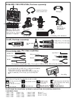
Radio control model Stick Sport 90 Instruction Manual Download Page 7

X

To muffler

Filler tube

To engine

Rubber
stopper

Cap

Stopper

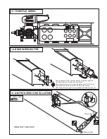
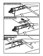
Align the engine center with fire-wall
marked line (A=A’)

FRONT VIEW

Using the four 3x20mm 
screws securing the  engine 
to the engine-mount

Align the mark on both 
mounts with the center 
mark on the fire-wall

!

A

A’

B

B=133 - 135mm

10- ENGINE INSTALLATION

Magnetic hatch

............4

......................4

4x25mm screw

Blind-nut

Summary of Contents for Stick Sport 90

Page 1: ...ty damage Before flying your airplane ensure the air field is spacious enough Always fly it outdoors in safe areas and seek professional advice if you are unexperienced ACHTUNG Dieses ferngesteuerte M...

Page 2: ...5 channel radio for airplane with 5 servos 120 4 cycle Silicone tube Extension for aileron servo retract servo 90 2 cycle REQUIRED FOR OPERATION Purchase separately Epoxy Glue 30 minute type TOLLS RE...

Page 3: ...VO USING 1 CONTROL HORN INSTALLATION 2 CONTROL HORN INSTALLATION 3 HORIZONTAL STABILIZER INSTALLATION 4 TAIL WHEEL INSTALLATION Cut away only the covering both side 6x45mm Nylon bolt 2 Plastic control...

Page 4: ...he trailing edge of the vertical stabilizer marking sure that the tail wheel gear is firmly seated in the slot in the rudder There should be a minimal hinge gap and the end of the rudder should not ru...

Page 5: ...VO ELEVATOR SERVO RUDDER SERVO RUDDER SERVO ELEVATOR SERVO IN CASE OF ONE RUDDER SERVO AND ONE ELEVATOR SERVO ON THE BOTTOM OF THE FUSELAGE USING IN CASE OF ONE RUDDER SERVO AND TWO ELEVATOR SERVO ON...

Page 6: ...3mm 6mm 9 MAIN LANDING GEAR INSTALLATION 6 6 4x15mm screw Blind nut 2 4X40mm screw 4 4mm nut 2 4mm washer 4 4 2mm collar 1 2 3 4...

Page 7: ...gine center with fire wall marked line A A FRONT VIEW Using the four 3x20mm screws securing the engine to the engine mount Align the mark on both mounts with the center mark on the fire wall A A B B 1...

Page 8: ...ere the four holes are to be drilled Remove the aluminum motor mounting plate and drill a 1 8 3mm hole through the fire wall at each of the four marks marked Note The aluminum motor mounting included...

Page 9: ...14 ALUMINUM TUBE INSTALLATION 15 WING INSTALLATION 16 WING INSTALLATION 5x20mm screw 5mm washer 2 2...

Page 10: ...ing they will not come loose or rattle during flight Never fly before checking the Cg s required position 99 106mm AILERON STROKE ELEVATOR STROKE RUDDER STROKE 19 32 15mm 1 3 16 30mm 51 64 20mm 1 3 16...

Reviews: