1.3
Installation
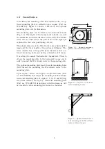
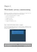
Figure 1.3:
Optional mounting
plate for the WaveGuide radar.
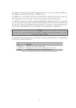
Figure 1.4: Top view of the hori-
zontal mounting beams.
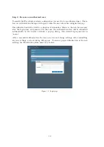
Figure 1.5: Optional frame that al-
lows mounting of the WaveGuide
radar at di
ff
erent angles.
To facilitate the mounting of the WaveGuide radar, an op-
tional mounting plate is available upon request (Part no.
WG-MP-SS). Figure 1.3 shows a sketch of the optional
mounting plate and its dimensions.
The mounting plate can be fixed to two horizontal beams
(Fig. 1.4). The length of the beams must take into account
the minimum horizontal distance between the WaveGuide
radar and any obstacles in the path of the radar signal (as
explained in the radar positioning criteria).
The outside diameter of the WaveGuide radar cylinder is 219
[mm] and the total height of the system is 245[mm]. The
radar cylinder has a flange (265 [mm] diameter) that con-
tains 4 mounting holes each having a diameter of 11 [mm].
It is advised to mount the horizontal beams first. Then to
attach the mounting plate to the horizontal beams and fi-
nally to mount the WaveGuide radar to the mounting plate.
The optional mounting plate has 4 threaded mounting holes
(M10 thread) for mounting the WaveGuide radar to the
mounting plate.
Upon request, Radac can supply an optional frame (Part
no. WG-MH-SS) that allows for mounting the WaveGuide
radar and mounting plate at angles 0, 5, 10, 15 and 20 [deg]
away from vertical (see Fig.1.5). The radar mounting plate
(Part no. WG-MP-SS) is included with this frame as well
as brackets to allow mounting the frame to a handrail.
5
Summary of Contents for WaveGuide 5 Onboard 2
Page 1: ...WaveGuide Onboard 2 User Manual...
Page 20: ...Figure 3 8 Dashboard view 17...


