1.3. Et power interfaces
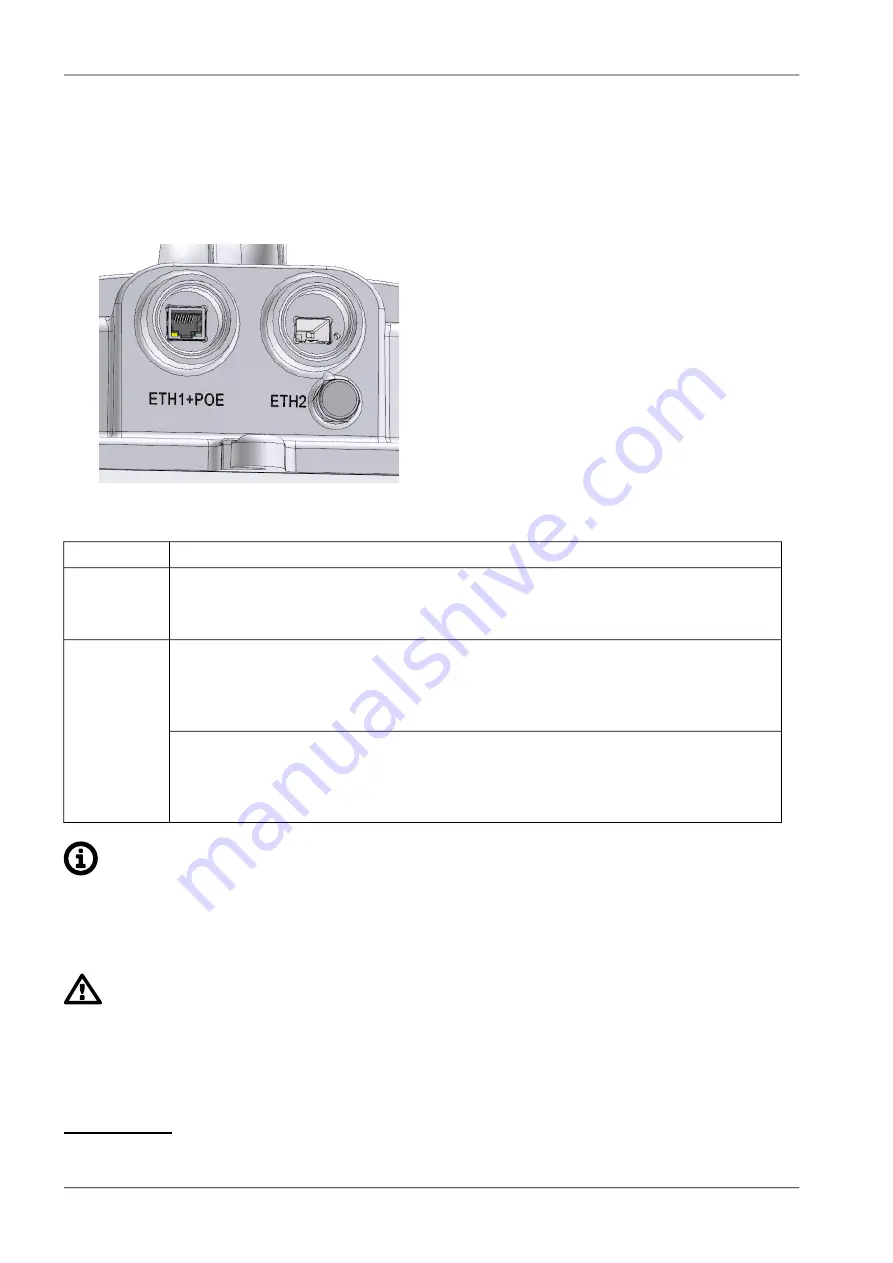
This chapter describes interfaces for user data transfer and power sourcing of the unit, as described
on the picture and characterized in the table below. Remaining interfaces for service purposes are
described in next chapter
Fig. 1.6: Slots ETH1+POE, ETH2
Function
Slot
Gigabit metallic Et Power over Ethernet (PoE) port
ETH1+POE
This port is capable of powering the unit with active or passive PoE power source
or with direct DC.
Slot for user exchangeable SFP module
ETH2
A wide range of fibre optics Ethernet modules is available. Both single or dual
mode transceivers can be used. SFP module with metallic RJ45 interface can also
be used.
The SFP LED
Located on SFP, just next to connectors. It is controlled by SFP module. Its function
is specific for each SFP module. The typical behavior is an indication the received
signal from the optical or metallic link to be within operational range.
Note
A set of all necessary bushing parts are delivered with each RAy unit - see a description of
this standard basic accessory
4
. Additional bushing options for installation of longer
connectors or other equipment are available as well. For bushings installation see
“Connectors assembly and disassembly”
Important
All bushings and plugs (including the original plugs in the flanges) must be fitted with O-rings
and carefully tightened. Otherwise, the unit is not protected against moisture intake through
connectors and cannot offer guaranteed functionality.
4
https://www.racom.eu/eng/products/microwave-link.html#accessories_kit
RAy3 Microwave Link – © RACOM s.r.o.
18
Product
Summary of Contents for RAy3-11
Page 2: ......


