background image


NOTE: IF NOT USING HOLLEY EFI SKIP TO PAGE 9 

 
CAN 

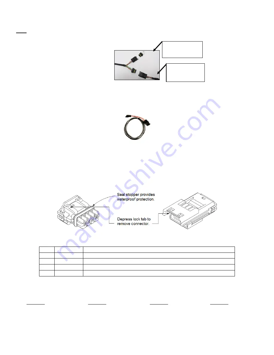
– Connect the harness from the CAN connector on the vehicle’s EFI main harness to the dash using the 

supplied male/female 

4’ CAN/Power extension.  Place the supplied terminator into the empty CAN connector.  

The terminator must be used at the end of the CAN cable. 


Holley EFI main harnesses use two types of CAN connectors.  Earlier harnesses use a 2 pin Metripak 
connector.  The kit includes an adapter to go from this to the 

4’ extension harness (note the white power and 

black ground wires are NOT needed for the Pro Dash, but need to be connected if other CAN devices require it 
for their power supply).  Later harnesses plug directl

y into the 4’ extension harness. 


Old Style CAN Adapter 


The CAN harness attached to the dash includes both male and female CAN connectors. These connectors are 
wired in parallel to allow daisy chaining of multiple devices on the CAN bus.   


Note that the Pro Dash does not use the CAN cabling to supply power and ground for it, unlike some other 
Holley EFI CAN devices, nor does the Pro Dash supply power to the CAN cabling, which is provided by the EFI 
harness.  


Pro Dash CAN Cable Description 

Pin 

Function 

Description 

+12V  

Power (pass through between connectors, not used for Pro Dash) 

CAN1H 

CAN_H Holley EFI communications 

CAN1L 

CAN_L Holley EFI communications 

GND 

Ground (pass through between connectors, not used for Pro Dash 


CAN Extension Harness 

 
The dash is supplied with a 4

’ CAN extension harness. Holley also offers the following replacement harnesses: 

558-451


– 1 foot 

558-452


– 4 feet 

558-453


– 8 feet 

558-454


– 12 feet 

 
Additional wires can be installed to use additional functions in the Pro Dash.  Consult the connector diagram 
and main user manual for more information. 
 

Install CAN 
terminator here. 

Male/Female 
CAN Extension 
Cable 

Summary of Contents for 250-DS-123

Page 1: ...Racepak Dash Quick Start Guide 250 DS 123 250 DS 686...

Page 2: ...reen Basics 10 Main Menu 10 Modifying Channels on a Preconfigured Layout 14 Saving Gauge Screens 14 Quick Save 14 Rename and Save 15 Building a Custom Gauge Screen 15 Add Gauges 15 Customizing the Gau...

Page 3: ...uct Package Contents Mounting There are two basic ways to mount the dash surface and flush mount Included with the contents of this kit are separate templates with a 1 1 layout for both methods The Fl...

Page 4: ...4...

Page 5: ...uous power is needed for a faster GPS lock and to keep the current date and time Clean a connection that does not share the same connections as dirty sources such as coils a starter solenoids fans etc...

Page 6: ...6...

Page 7: ...7...

Page 8: ...onnectors These connectors are wired in parallel to allow daisy chaining of multiple devices on the CAN bus Note that the Pro Dash does not use the CAN cabling to supply power and ground for it unlike...

Page 9: ...g receptacles USB 2 0 Connect the supplied locking cable to either of the USB ports on the back of the unit and tighten the thumbscrews This cable provides a type A receptacle that can accept USB flas...

Page 10: ...ith integrated finger pads that work with touchscreens The touchscreen is used for configuration and EFI tuning A stylus can be purchased if desired Make sure that it is for a capacitive touchscreen w...

Page 11: ...red Gauge Screens The following will appear the first time the dash is powered with an ECU connected or when changing to a different type of ECU Selecting Yes will load the appropriate default screens...

Page 12: ...12 Preconfigured Gauge Screens...

Page 13: ...13...

Page 14: ...that will allow the user to redefine the channel being displayed For instance RPM below could be changed to display Boost NOTE Only the gauge value being displayed will be updated The user MUST manua...

Page 15: ...gauge screen will be loaded by default at each power up If a specific default screen is desired go to the Main Menu and select Configuration then deselect Auto and select the desired initial layout nu...

Page 16: ...elect Customize B from the pop up menu In the scroll window you can see the parameters that are configurable Backup Restore A Backup and Restore option can be found under the Utilities menu Factory de...

Page 17: ...service 270 781 9741 or 1 866 464 6553 or they may be downloaded from our website https www holley com support resources Fuel_Injection To perform a firmware update follow these steps 1 Extract the c...

Reviews: