RaceGrade M GPS BL V2 User Manual Download Page 5

RaceGrade


GPS 


Page

  4 


Warm Up Time 


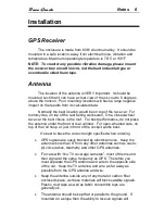
When the GPS receiver is first powered, it will start searching for 

satellites to lock onto.  This process takes time.  It will take longer the 
first time you power up at a new location from where you had previously 
turned it off.  Normal “cold” start up times, meaning being in a new area 
from the previous location, can be anywhere from 2 to 10 minutes.  
Subsequent “warm” start up times at the same location normally takes 
30 seconds to 2 minutes.  If you are outside of North American, expect 
the very first time to take up to 20 minutes. 

Internal Battery 

There is also now an internal battery to store the recent location during 
power off. This will aid in warm starts instead of cold starts, resulting in 
dramatically less time to lock onto satellites. The internal battery has a 
10 year life and is not user replaceable. After ten years please contact 
JGM Automotive Tooling for replacement. 


Status LEDs 

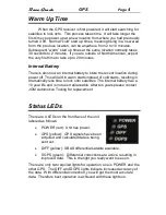
There are 4 LEDs on the front face of the unit 
labeled as follows: 


POWER (red):  Unit has power. 


GPS (yellow):  GPS signals have been 
acquired and calculated data is being 
sent out.  


DIFF (yellow):  SBAS differential satellite available. 


DGPS (green):  Differential corrections are active, resulting in 
improved data.  This is the light you really want to see on. 

There are only two required lights for operation, one is POWER and the 
other GPS.  The DIFF and DGPS lights indicate increased accuracy of 
the data.  With differential correction, you will get the most accurate 
data.  Therefore best operation is achieved with these lights on. 

Summary of Contents for M GPS BL V2

Page 1: ...RaceGrade GPS Part M GPS BL V2 Available in 10 Hz or 20 Hz USER MANUAL Version 2 2...

Page 2: ...s of JGM Automotive Tooling MoTeC is a registered trademark of MoTeC Pty The information in this document is subject to change without notice While every effort is taken to ensure correctness no respo...

Page 3: ...RS 232 Serial Output 5 CAN Output 5 20 Hz Update Option 5 Installation 6 GPS Receiver 6 Antenna 6 Loss of Signal 7 Setup for SDL ADL2 ADL3 ACL 8 i2 Analysis Math 9 Appendix 10 GPS Engine Specificatio...

Page 4: ...utes later Satellites used in the GPS solution are dynamically added or dropped based on signal quality Ideally you should have 8 or more satellites being tracked in order to obtain good accuracy Anyt...

Page 5: ...will aid in warm starts instead of cold starts resulting in dramatically less time to lock onto satellites The internal battery has a 10 year life and is not user replaceable After ten years please co...

Page 6: ...CAN bus speed operates at 1 mbit s and on the base ID of 0x146 The CAN output is based off the MoTeC GPS with STC serial to CAN Simply select the GPS Async template for MoTeC devices 20 Hz Update Opt...

Page 7: ...ce is the roof For best performance do not place the antenna under the front or rear window For open wheeled cars on top of the roll hoop or just in front of the cockpit works best It s best to have t...

Page 8: ...n a back and forth bundle Do not coil the extra antenna wire length in a circle or wrap it around anything Simply run the extra antenna wire back and forth Loss of Signal As mentioned earlier the ante...

Page 9: ...ecision Setup for SDL ADL2 ADL3 ACL For ADL2 SDL or ACL use please select the template GPS Standard RMC GGA listed under the communications RS 232 Verify 57 600 for the baud rate You ll be able to log...

Page 10: ...ogger logging them MoTeC s i2 has a built in Corrected GPS function found under the Tools pull down menu This function should only be used with data originating from a ADL2 SDL or ACL Actual shift may...

Page 11: ...ages available upon request Optional CAN output bus speed of 1 Mbit s Digital output pulse 0 5v with 50 duty cycle 94 Hz per 1 m s 940 Hz per 36 km h 1933 Hz per 46 mph 1 0638 cm per pulse can be conn...

Page 12: ...onnection The mating connector is a ASL 606 05SN pin 1 Ground negative battery do not use a 0v line pin 2 RS 232 Tx serial data out For ADL2 or ADL3 connect to pin 79 For SDL connect to pin 34 For ACL...

Reviews: