RABE drill control system
RDS ”Artemis II” for
Turbodrill Mega Seed
Turbodrill Fronttank T…F
Turbodrill Combi Speed T
Operating instructions
SW: PS 810 - 000 Rev. 006 GB
09.2003
Order-Nr. 9900.01.21GB01
Page 1: ...RABE drill control system RDS Artemis II for Turbodrill Mega Seed Turbodrill Fronttank T F Turbodrill Combi Speed T Operating instructions SW PS 810 000 Rev 006 GB 09 2003 Order Nr 9900 01 21GB01...
Page 2: ...2 Subject to technical change without notice 09 2003 09 2003 1 S1 S2 S3 S4 S5 I P R M ON OFF Back Enter Return...
Page 3: ...3 Subject to technical change without notice 09 2003...
Page 4: ...ettings 15 3 2 5 Warning parameters 15 3 2 6 Job management 15 3 3 Alarm screen 16 3 4 Function screen RATE 17 3 4 1 Display seed rate 17 3 4 2 Changing the rate on the move 17 3 5 INFO screen I 17 3...
Page 5: ...E settings 28 4 4 1 Machine type 28 4 4 2 Early start delay time pre start 28 a Calculate waiting time X 28 b Calculate reaction time Y 29 4 4 3 Hydraulics 29 4 4 4 TL tramline reduction 29 4 4 5 Sett...
Page 6: ...sily even without a manual Nevertheless please read the following information and explanations carefully In this way you will avoid errors in use and adjustment The operating terminal 2 1 has two M8 s...
Page 7: ...witch on the main switch After the controller terminal has been connected to the machine s job computer 4 3 the On Off button on the terminal lights up Press this button briefly to switch on the compu...
Page 8: ...Deviation factor nudge 0 Working width Tramline rhythm symmetric Seed rate in Ground wheel radar factor m per impulse radar factor Warning delay Over Under quantity steps Calibration speed Calibration...
Page 9: ...ly keep the lower left soft key S1 fig 8 pressed Then confirm this with the Enter key fig 7a d When the message Enter drill width is displayed enter the width via the keypad and confirm with Enter Wai...
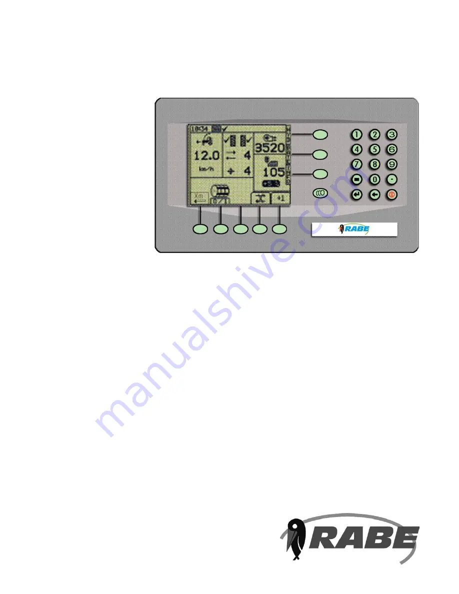
Page 10: ...ed drill For this purpose the display is divided into a number of areas At the very top is the Info bar with the time Below is a block display with speed of travel a tramline pattern and rhythm b fan...
Page 11: ...mber displays the tramline cycle counter If relaying is suppressed tramline stop the symbol has a line through it fig 9c The lower number displays the selected tramline rhythm When tramlines are activ...
Page 12: ...e carefully selected to avoid gaps or piling up when starting off Pre start can also be initiated when the machine is raised e g when turning at the start of the field to avoid a stop when sowing agai...
Page 13: ...nce the machine has been raised for 5 seconds S5 Modify tramline cycle Tramlines are relaid by raising the machine sowing stop or manually by the correction key S5 on the terminal When tramlines are a...
Page 14: ...that the standard parameters are loaded Please do not undertake any more changes at this point Further possibilities are described later Press key S3 ESC to return to the parameter menu P When the see...
Page 15: ...act unimportant which calibration area is used Using arrow keys S4 S5 the 1 100 ha or 1 40 ha can be varied upwards or downwards in steps A modification can also be made via the numerical pad Rule the...
Page 16: ...alues within the range of 33 to 300 of the predicted value Otherwise an error message is displayed and a repeat calibration is required If the value is unacceptable it will be necessary to enter a fic...
Page 17: ...eters but different values can be set using the numerical pad Thus it can on occasion be useful to switch off the warning function for a time Thus for example if the fan sensor is out of order fan mon...
Page 18: ...e the S5 key as a reminder For example if the machine has been switched off on one side the warning message Dosierwelle Metering Shaft is displayed immediately This can then be acknowledged by a key p...
Page 19: ...eed rate in kg ha as a reference The final value is the deviation in of the current seed rate from the calibrated value 3 4 2 Changing the rate on the move Use the keys S2 S3 fig 31 to increase or red...
Page 20: ...t the time and date to the current value If NO S5 is pressed the values remain unchanged The display changes automatically to the previous INFO screen 3 5 3 GRAND Use the GRAND key S3 to display the o...
Page 21: ...or b calibrate machine on the move The speed sensor factor is the actual distance travelled between two impulses from the ground wheel revolution counter or the radar The manufacturer s standard setti...
Page 22: ...n appears see fig 37 Now press ENTER and drive the machine off as normal Do not sow during the measurement i e the fan does not need to be at its nominal speed Once in motion the impulses are displaye...
Page 23: ...an be modified at any point in the run see 3 4 1 The rate step for this can be preset To do this move the marker arrow to the STEP line and set the desired percentage value using the right left arrow...
Page 24: ...he corresponding standard values are now assigned to the new seed type To do this place the marker arrow on the line below the new seed type and use the left right arrow keys to select either NORMAL S...
Page 25: ...e line kg rev Now enter the measured value using the numerical key pad and confirm with ENTER When ESC is pressed the parameter menu is again displayed It is not possible to modify the TGW here This c...
Page 26: ...et the metering devices and fill the machine Select winter wheat and calibrate as exactly as possible see 3 2 3 Before sowing check again that the sowing quantity is correctly shown as 200 kg ha on th...
Page 27: ...in the example there has therefore been 4 too much used Press ENTER now to confirm the value The display changes back to the seed type selection and displays the current seed type Note the value for k...
Page 28: ...d for the parameter menu screens the screen in fig 48 appears Now press the 1 key on the numerical pad to reach OPERATOR SETUP fig 49 Various settings 4 1 1 to 4 1 7 are possible To change the display...
Page 29: ...screen in fig 50 appears After this press key 2 on the numerical pad to get to DRILL CONFIG fig 51 Settings 4 2 1 to 4 2 3 are possible Motor control 1 Press the 3 key to get into MODULE CONFIG fig 5...
Page 30: ...e if additional equipment GPS Fieldstar is to be connected 4 3 3 Diagnosis Do not make any modifications here 4 3 4 HISTORY a This displays the total surface covered by the machine b An error evaluati...
Page 31: ...turn the ground wheel briefly or activate the radar briefly in order that some seed flows The time for the first seed to reach the bucket less one second is the correct waiting time X b Calculating re...
Page 32: ...value of 0 5 to 5 seconds When the pattern is switched a blockage interval of 15 seconds is activated during which the control system will not recogise any impulses for further pattern switching Now p...