User’s Manual
Hardware Reference
2–9
2.4
Programming Cable
The RabbitCore RCM2200 is automatically in pro-
gram mode when the
PROG
connector on the pro-
gramming cable is attached, and is automatically in
run mode when no programming cable is attached.
The
DIAG
connector of the programming cable
may be used on header J5 of the RabbitCore
RCM2200 with the board operating in the run
mode. This allows the programming port to be used
as an application port. See Appendix C, “Program-
ming Cable,” for more information.
2.4.1 Changing from Program Mode to
Run Mode
1.
Disconnect the programming cable from
header J5 of the RabbitCore RCM2200.
2.
Reset the RabbitCore RCM2200. You may
do this as explained in Figure 2–8.
The RabbitCore RCM2200 is now ready to operate
in the run mode.
2.4.2 Changing from Run Mode to
Program Mode
1.
Attach the programming cable to header J3
on the RabbitCore RCM2200 series.
2.
Reset the RabbitCore RCM2200 series. You
may do this as explained in Figure 2–8.
The RabbitCore RCM2200 is now ready to operate
in the program mode.
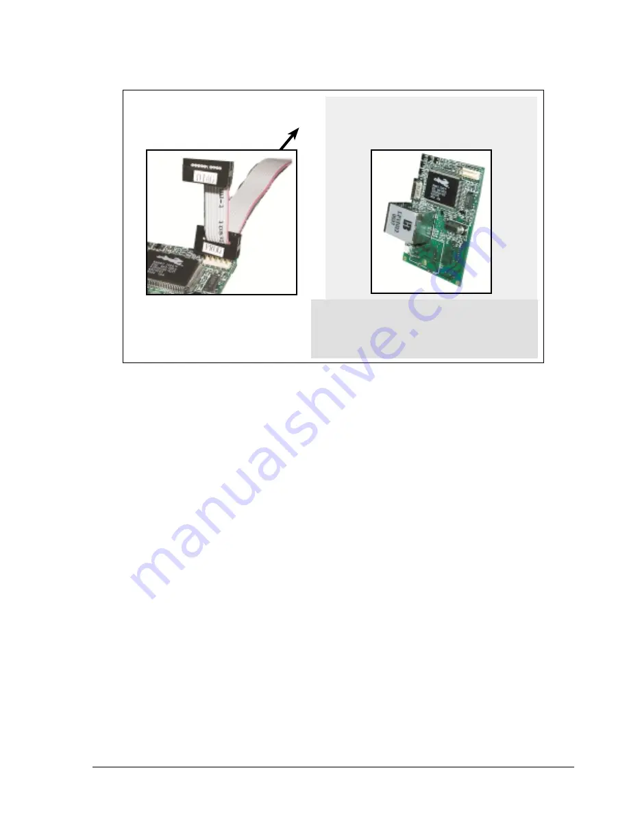
Figure 2–8:
Switching Between Program Mode and Run Mode
RESET RabbitCore when changing mode:
Short out pins 9 and 26 on header J5,
OR
Press
RESET
button (if using Prototyping Board),
OR
Remove, then reapply power
after removing or attaching programming cable.
To PC
COM
port
Run Mode
Program Mode
Summary of Contents for RCM2200
Page 1: ...RabbitCore RCM2200 C Programmable Module with Ethernet User s Manual 019 0097 010418 A...
Page 6: ...vi RabbitCore RCM2200...
Page 10: ...1 4 Introduction RabbitCore RCM2200...
Page 20: ...2 10 Hardware Reference RabbitCore RCM2200...
Page 26: ...3 6 Software Reference RabbitCore RCM2200...
Page 36: ...A 10 RabbitCore RCM2200 Specifications RabbitCore RCM2200...
Page 42: ...C 4 Programming Cable RabbitCore RCM2200...
Page 48: ...D 6 Sample Circuits RabbitCore RCM2200...
Page 50: ......
Page 52: ...E 4 External Interrupts RabbitCore RCM2200...
Page 57: ...C NONE...
Page 60: ......


