


Hardware Connections
To facilitate handling the Prototyping Board, snap in the four standoffs to the four holes at the corners
on the bottom side of the Prototyping Board before continuing with the remaining steps.
1. Attach Module to
Prototyping Board
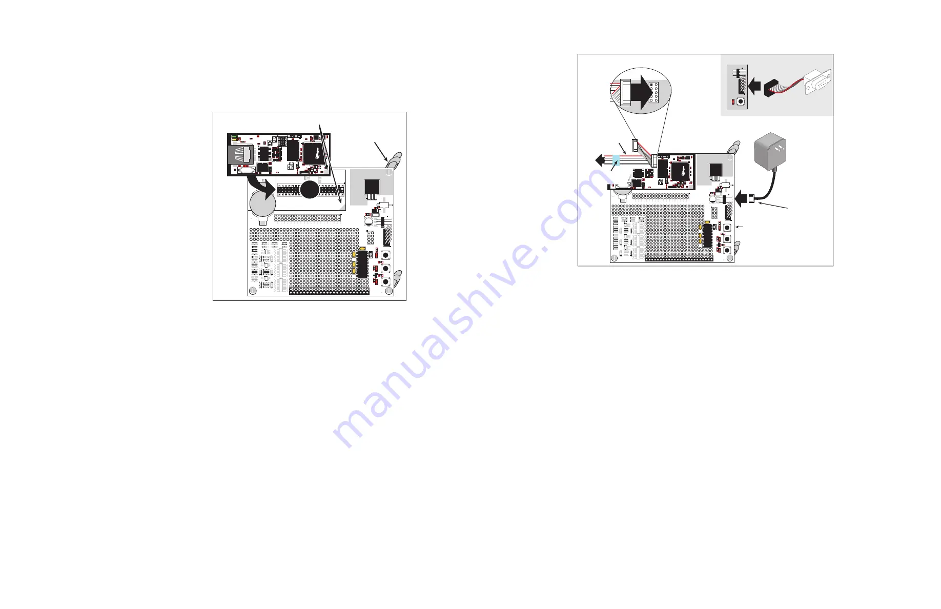
Turn the RCM3720 module so that
the Ethernet jack is on the left as
shown in Figure 1 below. Insert the
module’s J1 header into the J5 socket
on the Prototyping Board. The shaded
corner notch at the bottom right cor-
ner of the RCM3720 module should
face the same direction as the corre-
sponding notch below it on the Proto-
typing Board.
NOTE:
It is important that you
line up the pins on header J1 of
the RCM3720 module exactly
with the corresponding pins of
the J5 socket on the Prototyping
Board. The header pins may
become bent or damaged if the
pin alignment is offset, and the
module will not work. Perma-
nent electrical damage to the
module may also result if a mis-
aligned module is powered up.
Press the module’s pins firmly into the Prototyping Board socket.
2. Connect Programming Cable
The programming cable connects the RCM3720 to the PC running Dynamic C to download programs
and to monitor the RCM3720 module during debugging.
Attach the DE9 connector end of the programming cable to a COM (serial) port on the PC. Dynamic C
uses a COM port to communicate with the target system. The default selection is COM1, but you can
select a different COM port when you install Dynamic C or when you run it.
Connect the 10-pin connector of the programming cable labeled
PROG
to header J2 on the RCM3720
as shown in Figure 2. Be sure to orient the marked (usually red) edge of the cable towards pin 1 of
header J2. (Do not use the
DIAG
connector, which is used for a regular serial connection.)
NOTE:
Be sure to use the programming cable (part number 101-0542) supplied with this kit that
has blue shrink wrap around the RS-232 converter section located in the middle of the cable.
Programming cables from other Z-World or Rabbit Semiconductor kits were not designed to
work with RCM3720 modules.
NOTE:
Some PCs now come equipped only with a USB port. It may be possible to use some
RS-232/USB converters with the programming cable supplied with the Ethernet Connection
Kit. An RS-232/USB converter is available through the Z-World Web store.
Figure 1. Install the RCM3720 Module
on the Prototyping Board
Standoffs inserted
in mounting holes
+5V
VBA
T
PD5
/IORD
PG6
PE0
PE4
PE7
PC2
PB3
PB0
PF1
PA
1
PA
3
PA
5
PA
7
PC0
PF6
PF4
PB5
GND
GND
/RES
PD4
/IOWR
PG7
PE1
PE5
PC3/PG3
PC1/PG2
PF7
PF5
PB7
PB4
PB2
PF0
PA
0
PA
2
PA
4
PA
6
GND
GND
/RES
PD4
/I
OWR
PG7
PE1
PE5
PC3/PG3
PC1/PG2
PF1
PF5
PB7
PB4
PB2
PF0
PA
0
PA
2
PA
4
PA
6
+5V
VBA
T
PD5
/IORD
PG6
PE0
PE4
PE7
PC2
PC0
PF6
PF4
PB5
PB3
PB0
PF1
PA
1
PA
3
PA
5
PA
7
J4
PF4
PB7
PF6
PF7
SW1
SW2
DS1
DS2
J3
J1
J6
U2
C7
C2
C9 D1
C1
C14
U3
C1
1
C12
C13 C10
R6
J2
BT1
RCM3720 PROTOTYPING BOARD
CX1
CX2
RX7
RX8
RX9
RX10
RX11
RX12
RX13
RX14
RX15
RX16
RX5
CX14
CX13
RX6
UX9
CX12
CX10
CX5
CX3
CX6
UX7
CX4
RX1
CX9
RX2
UX8
RX4
CX11
RX3
UX3
UX2
UX1
CX8
CX7
J5
+5V
GND
PF7
R3
D2
R2
U1
C8
C5
C4
C6
C3
R4
R1
S3
PF4
R5
PB7
S2
S1
RESE
T
POWER
PF6
DS2
DS1
DS3
1
3
4
2
1
3
2
4
1
2
4
3
R24
R2
C18
C34
RP1
RP2
R18
R36
C35
C19
C26
C27
C28
R15
R16
C36
C39
R13
U1C25
JP1
C7
JP3
J2
C33
C32
C30
C31
C15
C17
C20
C38
C41
U4
R6
R11
C37
R4
R5
U5
C29
JP2
Y1
C40
C10
Q1
R7
C49
L2
L1
C14
C12
C22
U8
C23
Y3
C57
R31
C58
R29
DS2
R32
R30
DS1
J3
R34
C16
R28
T1
C24
C21
D1
U6
C53
R26
U3
R33
C8
U11
L4
L3
C54 C55
L6
R27
Align shaded
corners
RCM3720
J5
Figure 2. Connect Programming Cable and Power Supply
3. Connect Power
When all other connections have been made, you can connect power to the Prototyping Board. Con-
nect the AC adapter with the 3-pin connector to 3-pin header J1 on the Prototyping Board as shown in
Figure 2 above.
The connector may be attached either way as long as it is not offset to one side—
the center pin of J1 is always connected to the positive terminal, and either edge pin is negative
.
Plug in the AC adapter. The power LED beside the
RESET
button on the Prototyping Board should
light up. The RCM3720 and the Prototyping Board are now ready to be used. The
RESET
button is
provided on the Prototyping Board to allow a hardware reset without disconnecting power.
Alternate Power-Supply Connections
The 3-pin connector allows you to connect your own power supply—connect the center pin to the pos-
itive terminal, and connect either edge pin to the negative terminal. The power supply should deliver at
least 200 mA at 7.5 V–15 V DC.
Starting Dynamic C
Once the RCM3720 is connected as described in the preceding pages, start Dynamic C by double-clicking
on the Dynamic C icon or by double-clicking on
dcrabXXXX.exe
in the Dynamic C root directory,
where
XXXX
are version-specific characters. Dynamic C uses the serial port specified during installation.
If you are using a USB port to connect your computer to the RCM3720, choose
Options > Project
Options
and select “Use USB to Serial Converter.”
Run a Sample Program
Use the
File
menu to open the sample program
PONG.C
, which is in the Dynamic C
SAMPLES
folder.
Press function key
F9
to compile and run the program. The
STDIO
window will open on your PC and will
display a small square bouncing around in a box.
+5V
VBA
T
PD5
/IORD
PG6
PE0
PE4
PE7
PC2
PB3
PB0
PF1
PA
1
PA
3
PA
5
PA
7
PC0
PF6
PF4
PB5
GND
GND
/RES
PD4
/IOWR
PG7
PE1
PE5
PC3/PG3
PC1/PG2
PF7
PF5
PB7
PB4
PB2
PF0
PA
0
PA
2
PA
4
PA
6
GND
GND
/RES
PD4
/I
OWR
PG7
PE1
PE5
PC3/PG3
PC1/PG2
PF1
PF5
PB7
PB4
PB2
PF0
PA
0
PA
2
PA
4
PA
6
+5V
VBA
T
PD5
/IORD
PG6
PE0
PE4
PE7
PC2
PC0
PF6
PF4
PB5
PB3
PB0
PF1
PA
1
PA
3
PA
5
PA
7
J4
PF4
PB7
PF6
PF7
SW1
SW2
DS1
DS2
J3
J1
J6
U2
C7
C2
C9 D1
C1
C14
U3
C1
1
C12
C13 C10
R6
J2
BT1
RCM3720 PROTOTYPING BOARD
CX1
CX2
RX7
RX8
RX9
RX10
RX11
RX12
RX13
RX14
RX15
RX16
RX5
CX14
CX13
RX6
UX9
CX12
CX10
CX5
CX3
CX6
UX7
CX4
RX1
CX9
RX2
UX8
RX4
CX11
RX3
UX3
UX2
UX1
CX8
CX7
J5
+5V
GND
PF7
R3
D2
R2
U1
C8
C5
C4
C6
C3
R4
R1
S3
PF4
R5
PB7
S2
S1
RESE
T
POWER
PF6
DS2
DS1
DS3
1
3
4
2
1
3
2
4
1
2
4
3
J3
J1
S3
RESE
T
POWER
DS3
1
3
4
2
3-pin
Power Connector
AC Adapter
Reset Switch
RS-232
R24
R2
C18
C34
RP1
RP2
R18
R36
C35
C19
C26
C27
C28
R15
R16
C36
C39
R13
U1C25
JP1
C7
JP3
J2
C33
C32
C30
C31
C15
C17
C20
C38
C41
U4
R6
R11
C37
R4
R5
U5
C29
JP2
Y1
C40
C10
Q1
R7
C49
L2
L1
C14
C12
C22
U8
C23
Y3
C57
R31
C58
R29
DS2
R32
R30
DS1
J3
R34
C16
R28
T1
C24
C21
D1
U6
C53
R26
U3
R33
C8
U11
L4
L3
C54 C55
L6
R27
Colored
edge
To
PC
COM
port
Blue
shrink wrap
PROG
DIAG
Programming
Cable
PROG
J2
Prototyping
Board
Serial
Adapter Cable