


®
A Digi International
®
Company.
020–0086 • 050831–A
Z-World, Rabbit, and Dynamic C are registered trademarks of their
respective holders.
Color Touchscreen Application Kit
Getting Started
Application Kit Contents
•
Dynamic C
®
CD-ROM, with complete product documentation on disk.
•
Supplemental CD with sample programs and information related to Color Display Application Kit.
•
Reach Technologies supplemental CD with software for color display.
•
RCM3720 RabbitCore module.
•
RCM3720 Prototyping Board with RS-232 circuits installed.
•
Reach Technology SLCD controller board and color TFT touchscreen with screw-terminal power
connector and assembled serial cable interface.
•
Two AC adapters: 24 V DC (500 mA) with bare leads and 12 V DC, 1 A with 3-pin connector.
(AC adapters are included only with Application Kits
sold for the North American market).
•
Programming cable with level-matching circuitry.
•
DE9 to 10-pin serial adapter cable.
•
4 standoffs.
•
Getting Started
instructions.
•
Rabbit 3000 Processor Easy Reference
poster.
•
Registration card.
Using the Reach Technology Display
1. Locate the power-supply con-
nector and connect it to the
bare leads of an AC adapter
as shown in Figure 2. Pay
attention to the polarity of the
power-supply connections.
Attach the power-supply con-
nector to the display and
plug
in the AC adapter.
2. Use the serial cable interface
to connect the Reach Tech-
nologies display to an avail-
able COM port on your PC.
You may have to use a DE9
extension cable since the
serial cable interface is short.
3. Start the
BMPload.exe
program on the
Reach Tech-
nology
supplemental CD.
Select the serial COM port you are using and a baud rate of 115200. Press the
Load BMP List
button
and select the
demo.lst
file from the
Samples\ColorTouchscreen\BMP_Macro
folder on the
Dynamic C
supplemental CD. Next, press the
Add Macro File
button and select the
Macros.mac
file from the same folder on the Dynamic C supplemental CD. Finally press the
Store into SLCD
button to move these files to the Reach Technology display—this may take a few minutes. Press the
Quit
button to exit the
BMPload.exe
program when done.
4. Disconnect the serial cable interface from your PC COM port and use the serial adapter cable to connect
header J3 on the Prototyping Board to the serial cable interface as shown in Figure 2 to establish a serial
connection with the RCM3720. Reconnect the programming cable to the PC COM port if you had to dis-
connect it in order to use the PC COM port for the serial connection to the Reach Technology display in
the above steps.
Where Do I Go From Here?
You are now ready to go on to other sample programs and to develop your own applications. Application
Note AN411,
Color Touchscreen Application Kit
, takes you through loading and using the sample pro-
grams included with the Dynamic C supplemental CD, and describes Z-World’s software drivers.
The
RCM3700
User's Manual
provides complete hardware reference information and describes the software
function calls for the RCM3720 and the Prototyping Board. The Reach Technology supplemental CD con-
tains additional information about the display and its specifications.
Troubleshooting
•
The files loaded to the Reach Technology display should be from the
Dynamic C
supplemental CD.
•
Use the Dynamic C
Help
menu to get further assistance with Dynamic C.
•
Check the Z-World/Rabbit Semiconductor Technical Bulletin Board at
www.zworld.com/support/bb/
.
•
Use the Technical Support e-mail form at
www.zworld.com/support/
.
NOTE:
If you purchased your Color Touchscreen Kit through a distributor or through a Z-World
or Rabbit Semiconductor partner, contact the distributor or partner first for technical support.
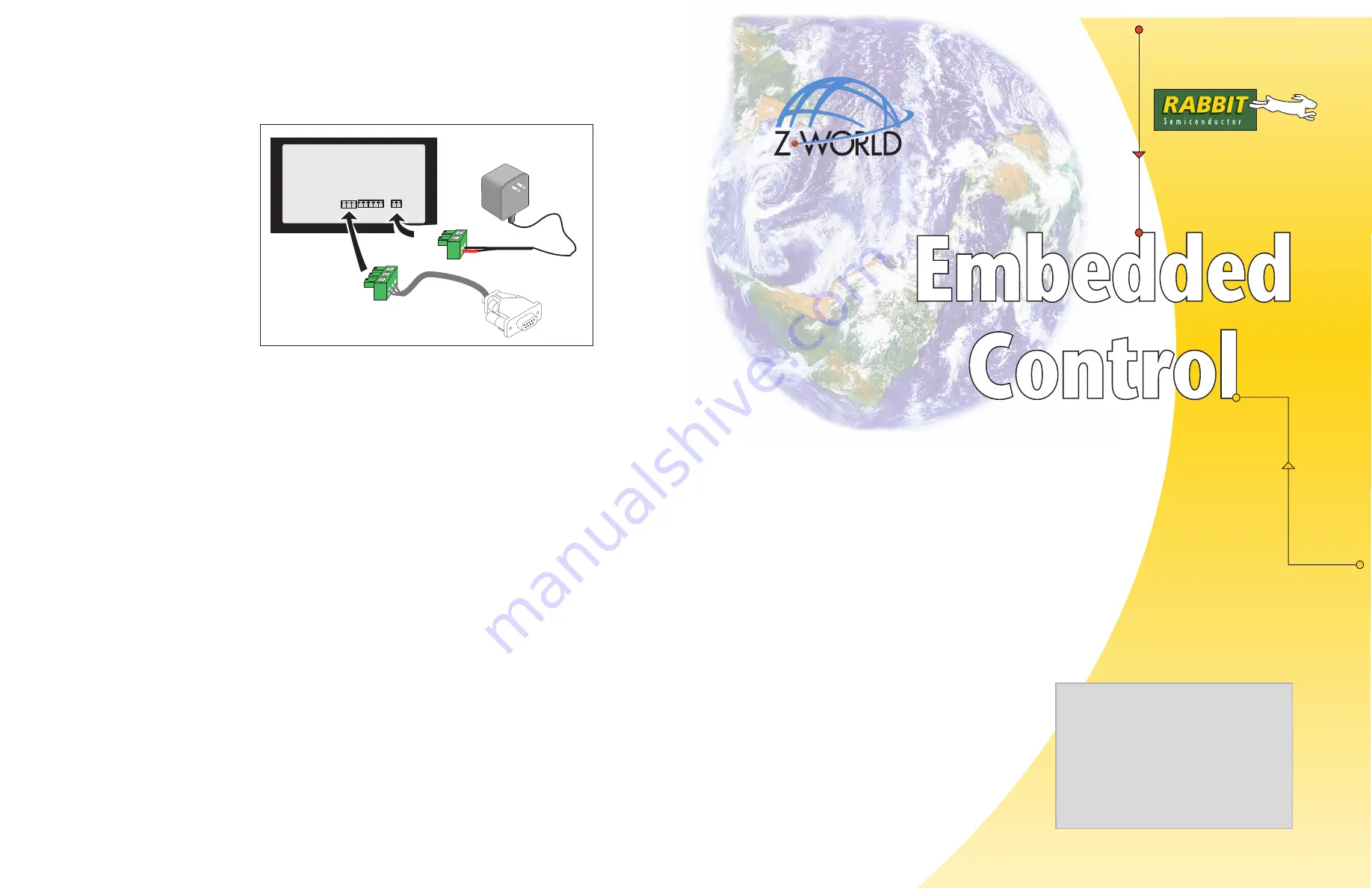
Figure 3. Reach Technology Display Connections
RS-232 RS-485
Power
+12 V GND
GND
+12 V
AC Adapter
Serial Cable
Interface
Installing Dynamic C
®
Insert the Dynamic C CD from the Applica-
tion Kit in your PC’s CD-ROM drive. If the
installation does not auto-start, run the
setup.exe
program in the root directory
of the Dynamic C CD. Install the software
from the Dynamic C supplemental CD after
you install Dynamic C


