background image

Instruction Reference Manual

105

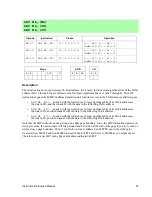
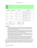
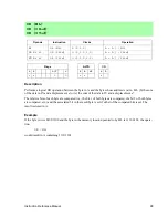
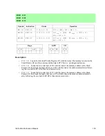
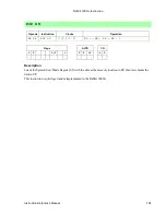
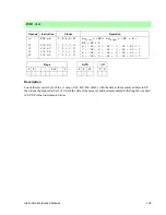
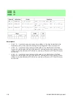
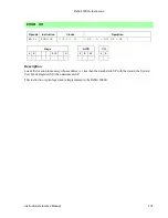
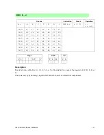
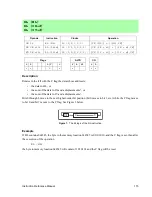
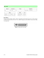
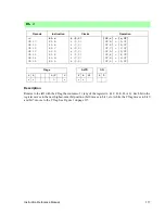
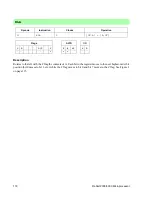
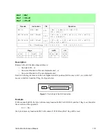
Description

Loads the low order byte of the zz (any of AF, BC, DE, or HL) with the data at the memory address in SP
then loads the high order byte of zz with the data at the memory address immediately following the one held
in SP. SP is then incremented twice.

POP

zz

Opcode

Instruction

Clocks

Operation

——

F1

C1

D1

E1

POP

zz

POP AF

POP BC

POP DE

POP HL

7 (2,1,2,2)

7 (2,1,2,2)

7 (2,1,2,2)

7 (2,1,2,2)

7 (2,1,2,2)

zz

(low)

= (SP);

zz

(high)

= (SP + 1);

SP = SP + 2

F = (SP); A = (SP + 1); SP = SP + 2

C = (SP); B = (SP + 1); SP = SP + 2

E = (SP); D = (SP + 1); SP = SP + 2

L = (SP); H = (SP + 1); SP = SP + 2

Flags

ALTD

I/O

S

Z

L/V

C

F

R

SP

S

D

-

-

-

-

Summary of Contents for 2000

Page 1: ...bit 2000 3000Microprocessor Instruction Reference Manual 019 0098 F 040114 This manual or an even more up to date revision is available for free download at the Rabbit website www rabbitsemiconductor...

Page 2: ...ii Rabbit 2000 3000 Microprocessor...

Page 3: ...Table of Contents 1 Alphabetical Listing of Instructions 1 2 Instructions Listed by Group 3 3 Document Conventions 7 4 Processor Registers 11 5 OpCode Descriptions 13 6 Opcode Map 153 7 Quick Referen...

Page 4: ...iv Rabbit 2000 Microprocessor...

Page 5: ...E HL 46 EX SP HL 43 EX SP IX 44 EX SP IY 44 EXX 47 I IDET 48 INC IX 50 INC IY 50 INC r 51 INC ss 52 INC HL 49 INC IX d 49 INC IY d 49 IOE 53 IOI 53 IPRES 55 IPSET 0 54 IPSET 1 54 IPSET 2 54 IPSET 3 54...

Page 6: ...107 PUSH zz 108 R RA 126 RDMODE 109 RES b r 111 RES b HL 110 RES b IX d 110 RES b IY d 110 RET 112 RET f 113 RETI 114 RL DE 116 RL r 117 RL HL 115 RL IX d 115 RL IY d 115 RLA 118 RLC r 120 RLC HL 119...

Page 7: ...exed Load and Store LD HL d HL 62 LD IX d HL 63 LD IY d HL 64 LD SP n HL 66 LD SP n IX 66 LD SP n IY 66 LD HL HL d 74 LD HL IX d 74 LD HL IY d 74 LD HL SP n 75 LD IX SP n 78 LD IY SP n 81 E 16 bit Loa...

Page 8: ...R IX 124 RR IY 124 SBC HL ss 133 I 16 bit Arithmetic Logical and Rotate AND HL DE 25 AND IX DE 25 AND IY DE 25 J 8 bit Arithmetic and Logical ADC A HL 13 ADC A IX d 13 ADC A IY d 13 ADC A n 14 ADC A r...

Page 9: ...HL 119 RLC IX d 119 RLC IY d 119 RLC r 120 RR HL 122 RR IX d 122 RR IY d 122 RR r 125 RRC HL 127 RRC IX d 127 RRC IY d 127 RRC r 128 SLA HL 138 SLA IX d 138 SLA IY d 138 SLA r 139 SRA HL 140 SRA IX d...

Page 10: ...ES 55 IPSET 0 54 IPSET 1 54 IPSET 2 54 IPSET 3 54 LD A XPC 69 LD SP HL 85 LD SP IX 85 LD SP IY 85 LD XPC A 86 POP IP 103 RETI 114 U Rabbit 3000A Instructions IDET 48 LDDSR 88 LDISR 88 LSDDR 95 LSDR 95...

Page 11: ...sis are a breakdown of the total clocks The number of clocks instructions take follows a general patern There are several Rabbit instructions that do not adhere to this pattern Some instructions take...

Page 12: ...on register ALTD operation is a special case Flag Description S D IOI and IOE affect destination IOI and IOE affect source S Z L V C Description Sign flag affected Sign flag not affected Zero flag aff...

Page 13: ...to PC f f condition code select 000 NZ 001 Z 010 NC 011 C 100 LZ NV 101 LO V 110 P 111 M m m the most significant bits MSB of a 16 bit constant mn mn 16 bit constant n n 8 bit constant or the least si...

Page 14: ...Carry C 0 C C 1 Carry C 1 P S 0 Positive M S 1 Minus LZ L V 0 For logic operations Logic Zero all of the four most significant bits of the result are zero NV L V 0 For arithmentic operations No Overfl...

Page 15: ...PC Index Register Index Register Stack Pointer Program Counter General Purpose External Interrupt Internal Interrupt Interrupt Priority Extension of Program Counter EIR IIR IP XPC Accumulator Flags H...

Page 16: ...12 Rabbit 2000 3000 Microprocessor...

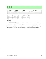
Page 17: ...or the sum of the data in IX and a displacement value d or the sum of the data in IY and a displacement value d The result is then stored in A ADC A HL ADC A IX d ADC A IY d Opcode Instruction Clocks...

Page 18: ...ocessor Description The 8 bit constant n is summed with the C flag and with the data in A The sum is then stored in A ADC A n Opcode Instruction Clocks Operation CE n ADC A n 4 2 2 A A n CF Flags ALTD...

Page 19: ...the registers A B C D E H or L The result is stored in A ADC A r Opcode Instruction Clocks Operation ADC A r 2 A A r CF 8F ADC A A 2 A A A CF 88 ADC A B 2 A A B CF 89 ADC A C 2 A A C CF 8A ADC A D 2...

Page 20: ...a in ss any of BC DE HL or SP The result is stored in HL ADC HL ss Opcode Instruction Clocks Operation ADC HL ss 4 2 2 HL HL ss CF ED 4A ADC HL BC 4 2 2 HL HL BC CF ED 5A ADC HL DE 4 2 2 HL HL DE CF E...

Page 21: ...um of the data in IX and a displacement value d or the sum of the data in IY and a displacement value d The result is stored in A ADD A HL ADD A IX d ADD A IY d Opcode Instruction Clocks Operation 86...

Page 22: ...3000 Microprocessor Description The data in A is summed with the 8 bit constant n The result is stored in A ADD A n Opcode Instruction Clocks Operation C6 n ADD A n 4 2 2 A A n Flags ALTD I O S Z L V...

Page 23: ...of the registers A B C D E H or L The result is stored in A ADD A r Opcode Instruction Clocks Operation ADD A r 2 A A r 87 ADD A A 2 A A A 80 ADD A B 2 A A B 81 ADD A C 2 A A C 82 ADD A D 2 A A D 83 A...

Page 24: ...with the data in the ss any of BC DE HL or SP The result is stored in HL ADD HL ss Opcode Instruction Clocks Operation 09 19 29 39 ADD HL ss ADD HL BC ADD HL DE ADD HL HL ADD HL SP 2 2 2 2 2 HL HL ss...

Page 25: ...stored in IY ADD IX xx ADD IY yy Opcode Instruction Clocks Operation DD 09 DD 19 DD 29 DD 39 ADD IX xx ADD IX BC ADD IX DE ADD IX IX ADD IX SP 4 2 2 4 2 2 4 2 2 4 2 2 4 2 2 IX IX xx IX IX BC IX IX DE...

Page 26: ...sor Description The data in the Stack Pointer register SP is summed with the 7 bit signed displacement d and then stored in SP ADD SP d Opcode Instruction Clocks Operation 27 d ADD SP d 4 2 2 SP SP d...

Page 27: ...causes special alternate register uses unique to that instruction Example The instruction ALTD ADD HL DE would add the data in DE to the data in HL and store the result in the alternate register HL Th...

Page 28: ...ytes are com pared etc The associated bit in the result byte is set only if both the compared bits are set The result is stored in A Example If the byte in A contains the value 1011 1100 and the byte...

Page 29: ...nd the word in DE The result is stored in IX AND IY DE performs a logical AND operation between the word in IY and the word in DE The result is stored in IY The relative bits of each byte are compared...

Page 30: ...relative bits of each byte are compared i e bit 0 of both bytes are compared bit 1 of both bytes are compared etc The associ ated bit in the result byte is set only if both the compared bits are set...

Page 31: ...i e bit 0 of both bytes are compared bit 1 of both bytes are compared etc The associated bit in the result byte is set only if both the compared bits are set The result is stored in A AND r Opcode Ins...

Page 32: ...HL bit 4 HL bit 5 HL bit 6 HL bit 7 DD CB d 46 DD CB d 4E DD CB d 56 DD CB d 5E DD CB d 66 DD CB d 6E DD CB d 76 DD CB d 7E BIT b IX d BIT 0 IX d BIT 1 IX d BIT 2 IX d BIT 3 IX d BIT 4 IX d BIT 5 IX...

Page 33: ...the tested bit is 0 reset if the bit is 1 BIT b r Opcode Instruction Clocks Operation b r A B C D E H L BIT b r 4 2 2 r bit CB 0 47 40 41 42 43 44 45 CB 1 4F 48 49 4A 4B 4C 4D CB 2 57 50 51 52 53 54 5...

Page 34: ...it 2000 3000 Microprocessor Description If the data in HL does not equal zero then it is set to 1 BOOL HL Opcode Instruction Clocks Operation CC BOOL HL 2 If HL 0 HL 1 Flags ALTD I O S Z L V C F R SP...

Page 35: ...ption If the data in IX or IY does not equal zero then that register is set to 1 BOOL IX BOOL IY Opcode Instruction Clocks Operation DD CC BOOL IX 4 2 2 If IX 0 IX 1 FD CC BOOL IY 4 2 2 If IY 0 IY 1 F...

Page 36: ...the low order byte PC is then loaded with mn 16 bit address of the first instruction of the subroutine SP is updated to reflect the two bytes pushed onto the stack The Dynamic C assembler recognizes C...

Page 37: ...Reference Manual 33 Description The C flag is inverted If it is set it becomes cleared If it is not set it becomes set CCF Opcode Instruction Clocks Operation 3F CCF 2 CF CF Flags ALTD I O S Z L V C...

Page 38: ...here x is HL IX d or IY d and V indicates that the overflow flag is set on an arithmetic overflow result That is the overflow flag is set when the operands have different signs and the sign of the res...

Page 39: ...ag is set on an arithmetic overflow result That is the overflow flag is sig nalled when the operands have different signs and the sign of the result is different from the argument you are subtracting...

Page 40: ...rflow flag is set on an arithmetic overflow result That is the overflow flag is signalled when the operands have different signs and the sign of the result is different from the argument you are subtr...

Page 41: ...Description The data in A is inverted one s complement Example If the data in A is 1100 0101 after the instruction CPL A will contain 0011 1010 CPL Opcode Instruction Clocks Operation 2F CPL 2 A A Fla...

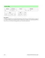
Page 42: ...ata in IX plus a displacement value d or the data in IY plus a displacement value d DEC HL DEC IX d DEC IY d Opcode Instruction Clocks Operation 35 DEC HL 8 2 1 2 3 HL HL 1 DD 35 d DEC IX D 12 2 2 2 1...

Page 43: ...ion Reference Manual 39 Description Decrements the data in IX or IY DEC IX DEC IY Opcode Instruction Clocks Operation DD 2B DEC IX 4 2 2 IX IX 1 FD 2B DEC IY 4 2 2 IY IY 1 Flags ALTD I O S Z L V C F R...

Page 44: ...data in r any of the registers A B C D E H or L DEC r Opcode Instruction Clocks Operation 3D 05 0D 15 1D 25 2D DEC r DEC A DEC B DEC C DEC D DEC E DEC H DEC L 2 2 2 2 2 2 2 2 r r 1 A A 1 B B 1 C C 1...

Page 45: ...scription Decrements the data in ss any of BC DE HL or SP DEC ss Opcode Instruction Clocks Operation 0B 1B 2B 3B DEC ss DEC BC DEC DE DEC HL DEC SP 2 2 2 2 2 ss ss 1 BC BC 1 DE DE 1 HL HL 1 SP SP 1 Fl...

Page 46: ...data in B then if the data in B does not equal 0 it adds the 8 bit signed constant e to PC 2 is subtracted from the value e so the instruction jumps from the current instruction and not the following...

Page 47: ...te in H with the data whose address is the data in SP plus 1 and exchanges the byte in L with the data whose address is the data in SP EX SP HL Opcode Instruction Clocks Operation ED 54 EX SP HL 15 2...

Page 48: ...tack Pointer register SP EX SP IY exchanges the high order byte of IY with the data whose address is 1 plus the data in the Stack Pointer register and exchanges the low order byte of IY with the data...

Page 49: ...ction Reference Manual 45 Description Exchanges the data in AF with the data in the alternate register AF EX AF AF Opcode Instruction Clocks Operation 08 EX AF AF 2 AF AF Flags ALTD I O S Z L V C F R...

Page 50: ...e ALTD instruction is present then the data in DE is exchanged with the data in the alternate register HL The Dynamic C assembler recognizes the following instructions which are based on a combination...

Page 51: ...nual 47 Description Exchanges the data in BC DE and HL with the data in their respective alternate registers BC DE and HL EXX Opcode Instruction Clocks Operation D9 EXX 2 BC BC DE DE HL HL Flags ALTD...

Page 52: ...ote that IDET has the same opcode value as LD E E and actually executes that opcode as well as the behav ior described above If IDET is prefixed by ALTD the opcode LD E E is executed and the special S...

Page 53: ...data in IX and a displacement value d or the sum of the data in IY and a displacement value d INC HL INC IX d INC IY d Opcode Instruction Clocks Operation 34 INC HL 8 2 1 2 3 HL HL 1 DD 34 d INC IX d...

Page 54: ...rocessor Description INC IX increments the data in IX INC IY increments the data in IY INC IX INC IY Opcode Instruction Clocks Operation DD 23 INC IX 4 2 2 IX IX 1 FD 23 INC IY 4 2 2 IY IY 1 Flags ALT...

Page 55: ...ata in r any of the registers A B C D E H or L INC r Opcode Instruction Clocks Operation 3C 04 0C 14 1C 24 2C INC r INC A INC B INC C INC D INC E INC H INC L 2 2 2 2 2 2 2 2 r r 1 A A 1 B B 1 C C 1 D...

Page 56: ...Description Increments the data in ss any of BC DE HL or SP INC ss Opcode Instruction Clocks Operation 03 13 23 33 INC ss INC BC INC DE INC HL INC SP 2 2 2 2 2 ss ss 1 BC BC 1 DE DE 1 HL HL 1 SP SP 1...

Page 57: ...or external I O operations By default writes are inhibited for external I O operations and fifteen wait states are added for I O accesses WARNING If an I O prefixed instruction is immediately followed...

Page 58: ...ing the previous pri orities 2 bits to the left then sets the Interrupt Priority Register bits 0 and 1 to 10 IPSET 3 The IPSET 3 instruction shifts the contents of the register holding the previous pr...

Page 59: ...s priority It is impossible to interrupt during the execution of this instruction This instruction is privileged Example If the Interrupt Priority register contains 00000110 the execution of the instr...

Page 60: ...data in IY is loaded into PC Thus the address of the next instruction fetched is the data in IY JP mn The 16 bit constant mn is loaded into PC Thus the address of the next instruction fetched is mn T...

Page 61: ...P S flag not set M S flag set This instruction recognizes labels when used in the Dynamic C assembler JP f mn Opcode Instruction Clocks Operation C2 n m CA n m D2 n m DA n m E2 n m EA n m F2 n m FA n...

Page 62: ...m the displacement value so that the displacement takes place from the instruction opcode This instruction recognizes labels when used in the Dynamic C assembler JR cc e Opcode Instruction Clocks Oper...

Page 63: ...ments of PC to complete two is subtracted from the displacement value so that the displacement takes place from the instruction opcode This instruction recognizes labels when used in the Dynamic C ass...

Page 64: ...is pushed onto the stack the high order byte first then the low order byte Then the XPC is loaded with the 8 bit value x and the PC is loaded with the 16 bit value mn The SP is then updated to reflec...

Page 65: ...stant n LD HL r Loads the memory location whose address is the data in HL with the data in r any of the registers A B C D E H or L LD BC A LD DE A LD HL n LD HL r Opcode Instruction Clocks Operation...

Page 66: ...e sum of the data in HL and a displacement value d Then loads the data in H into the memory location whose address is the sum of the data in HL and a displacement value d plus 1 LD HL d HL Opcode Inst...

Page 67: ...the data in r any of the registers A B C D E H or L into the mem ory location whose address is the sum of the data in IX plus a displacement value d LD IX d HL LD IX d n LD IX d r Opcode Instruction C...

Page 68: ...oads the data in r any of the registers A B C D E H or L into the mem ory location whose address is the sum of the data in IY plus a displacement value d LD IY d HL LD IY d n LD IY d r Opcode Instruct...

Page 69: ...whose address is 1 plus mn with the high order byte of the data in IY into LD mn ss Loads the memory location whose address is mn with the low order byte of the data in ss any of BC DE HL or SP Then l...

Page 70: ...byte of the data in IX into the memory location whose address is the sum of data in SP the displacement n and 1 LD SP n IY Loads the low order byte of the data in IY into the memory location whose add...

Page 71: ...a whose address in memory is the data in BC or the data in DE or the 16 bit constant mn LD A BC LD A DE LD A mn Opcode Instruction Clocks Operation 0A LD A BC 6 2 2 2 A BC 1A LD A DE 6 2 2 2 A DE 3A n...

Page 72: ...orm the 16 bit ISR starting address LD A IIR Loads A with the data in the Internal Interrupt Register IIR The IIR is used to specify the Most Significant Byte MSB of the Internal Peripheral Interrupt...

Page 73: ...ction Reference Manual 69 Description Loads A with the data in XPC This instruction is privileged LD A XPC Opcode Instruction Clocks Operation ED 77 LD A XPC 4 2 2 A XPC Flags ALTD I O S Z L V C F R S...

Page 74: ...ter dd with data at memory address mn plus 1 LD dd mn Opcode Instruction Clocks Operation ED 4B n m ED 5B n m ED 6B n m ED 7B n m LD dd mn LD BC mn LD DE mn LD HL mn LD SP mn 13 2 2 2 2 1 2 2 13 2 2 2...

Page 75: ...the data in BC or DE LD dd BC LD dd DE Opcode Instruction Clocks Operation ED 49 ED 59 ED 69 LD dd BC LD BC BC LD DE BC LD HL BC 4 2 2 4 2 2 4 2 2 4 2 2 dd BC BC BC DE BC HL BC ED 41 ED 51 ED 61 LD dd...

Page 76: ...BC DE HL or SP with the 16 bit value mn LD dd mn Opcode Instruction Clocks Operation 01 n m 11 n m 21 n m 31 n m LD dd mn LD BC mn LD DE mn LD HL mn LD SP mn 6 2 2 2 6 2 2 2 6 2 2 2 6 2 2 2 6 2 2 2 dd...

Page 77: ...m the 16 bit ISR starting address LD IIR A Loads the Internal Interrupt Register IIR with the data in A The IIR is used to specify the Most Significant Byte MSB of the Internal Peripheral Interrupt ad...

Page 78: ...n IX plus a displacement d Then loads H with the data whose address is the data in IX plus a displacement d plus 1 LD HL IY d Loads L with the data whose address is the data in IY plus a displacement...

Page 79: ...hose address is the data in SP plus a displacement d Then loads H with the data whose address is the data in SP plus a displacement d plus 1 LD HL SP n Opcode Instruction Clocks Operation C4 n LD HL S...

Page 80: ...r Description LD HL IX Loads HL with the data in IX LD HL IY Loads HL with the data in IY LD HL IX LD HL IY Opcode Instruction Clocks Operation DD 7C LD HL IX 4 2 2 HL IX FD 7C LD HL IY 4 2 2 HL IY Fl...

Page 81: ...of IX with the data whose address is mn Then loads the high order byte of IX with the data whose address is mn plus 1 LD IX mn Opcode Instruction Clocks Operation DD 2A n m LD IX mn 13 IX low mn IX hi...

Page 82: ...ck Pointer SP plus a dis placement n Then loads the high order byte of IX with the data whose address is the data in the Stack Pointer register plus a displacement n plus 1 LD IX SP n Opcode Instructi...

Page 83: ...nt mn LD IY HL Loads IY with the data in HL LD IX mn Loads IY with the 16 bit constant mn LD IX HL LD IX mn LD IY HL LD IY mn Opcode Instruction Clocks Operation DD 7D LD IX HL 4 2 2 IX HL DD 21 n m L...

Page 84: ...byte of IY with the data at the address mn and loads the high order byte of IY with the data at the address mn 1 LD IY mn Opcode Instruction Clocks Operation FD 2A n m LD IY mn 13 IY low mn IY high m...

Page 85: ...nter register SP plus a displacement n Then loads the high order byte of IY with the data whose address is the data in the Stack Pointer register plus a displacement n plus 1 LD IY SP n Opcode Instruc...

Page 86: ...r HL A HL B HL C HL D HL E HL H HL L HL DD 7E d DD 46 d DD 4E d DD 56 d DD 5E d DD 66 d DD 6E d LD r IX d LD A IX d LD B IX d LD C IX d LD D IX d LD E IX d LD H IX d LD L IX d 9 2 2 2 1 2 9 2 2 2 1 2...

Page 87: ...H or L with the 8 bit constant n LD r n Opcode Instruction Clocks Operation 3E n 06 n 0E n 16 n 1E n 26 n 2E n LD r n LD A n LD B n LD C n LD D n LD E n LD H n LD L n 4 2 2 4 2 2 4 2 2 4 2 2 4 2 2 4 2...

Page 88: ...g any of the registers A B C D E H or L LD r g Opcode Instruction Clocks Operation r g A B C D E H L LD r g 2 r g A 7F 78 79 7A 7B 7C 7D B 47 40 41 42 43 44 45 C 4F 48 49 4A 4B 4C 4D D 57 50 51 52 53...

Page 89: ...he data in a HL b the data in IX or c the data in IY These are privileged instructions LD SP HL LD SP IX LD SP IY Opcode Instruction Clocks Operation F9 LD SP HL 2 SP HL DD F9 LD SP IX 4 2 2 SP IX FD...

Page 90: ...it 2000 3000 Microprocessor Description Loads XPC with the data in A This instruction is privileged LD XPC A Opcode Instruction Clocks Operation ED 67 LD XPC A 4 2 2 XPC A Flags ALTD I O S Z L V C F R...

Page 91: ...l BC equals zero If any of these block move instructions are prefixed by IOI or IOE the destination will be in the specified I O space Add 1 clock for each iteration for the prefix if the prefix is IO...

Page 92: ...f this instruction is prefixed by IOI or IOE the destination will be in the specified I O space Add 1 clock for each iteration for the prefix if the prefix is IOI internal I O If the prefix is IOE add...

Page 93: ...H LDP IY HL Loads the memory location whose 16 least significant bits of its 20 bit address are the data in IY with the data in L and then loads the following 20 bit address with the data in H Note th...

Page 94: ...IY Loads the memory location whose 16 least significant bits of its 20 bit address are the 16 bit constant mn with the low order byte of IY and then loads the following memory location with the high...

Page 95: ...Loads L with the data whose 16 least significant bits of its 20 bit address are the data in IY and then loads H with the data in the following 20 bit address Note that the LDP instructions wrap aroun...

Page 96: ...low order byte of IY with the data whose 16 least significant bits of its 20 bit address are the 16 bit constant mn and then loads the high order byte of IY with the data in the following 20 bit addr...

Page 97: ...in XMEM Note that the value of XPC and consequently the address space defined by the XPC is dynamically changed with the LJP instructions The instruction loads the XPC with the 8 bit constant x Then l...

Page 98: ...der byte of PC is loaded with the data whose address is in SP Next the high order byte of PC is loaded with the data whose address is one plus the data in SP and XPC is loaded with the data whose addr...

Page 99: ...C does not equal 0 the memory location whose address is in DE is loaded with the data ta the address in HL The data in BC is then decremented and DE incre mented the data in HL remains unchanged This...

Page 100: ...aced in HL bits 31 through 16 and BC bits 15 through 0 registers Examples LD BC 0FFFFh BC gets 1 LD DE 0FFFFh DE gets 1 MUL HL BC 1 HL gets 0000h BC gets 0001h In the above example the 2 s complement...

Page 101: ...on Reference Manual 97 Description Subtracts the value of the data in A from zero and stores the result in A NEG Opcode Instruction Clocks Operation ED 44 NEG 4 2 2 A 0 A Flags ALTD I O S Z L V C F R...

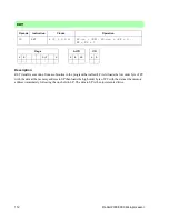
Page 102: ...98 Rabbit 2000 3000 Microprocessor Description No operation is performed during this cycle NOP Opcode Instruction Clocks Operation 00 NOP 2 No operation Flags ALTD I O S Z L V C F R SP S D...

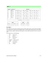
Page 103: ...red the bit 2 of both bytes are compared etc and the associated bit in the result byte is set if either of the compared bits is set The result is stored in A Example If the byte in A is 0100 1100 and...

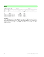
Page 104: ...of each byte are compared i e the bit 1 of both bytes are compared the bit 2 of both bytes are compared etc and the associated bit in the result byte is set if either of the compared bits is set The r...

Page 105: ...IY and the data in DE The result is stored in IY The relative bits of each byte are compared i e the bit 1 of both bytes are compared the bit 2 of both bytes are compared etc and the associated bit in...

Page 106: ...tive bits of each byte are compared i e bit 1 of both bytes are compared bit 2 of both bytes are com pared etc and the associated bit in the result byte is set if either of the compared bits is set Th...

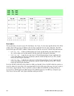
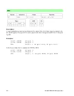
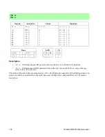
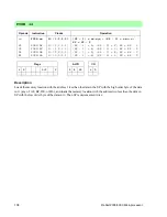
Page 107: ...at the address immediately follow ing the one held in SP SP is then incremented twice POP IY Loads the low order byte of IY with the data at the memory address in the Stack Pointer SP then loads the...

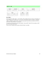
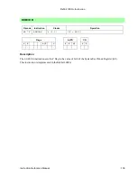
Page 108: ...em User Mode Register SU with the data at the memory location in SP then increments the data in SP This instruction is privileged and is implemented in the Rabbit 3000A POP SU Opcode Instruction Clock...

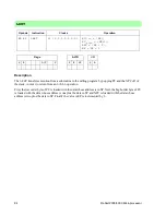
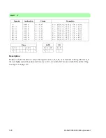
Page 109: ...he data at the memory address immediately following the one held in SP SP is then incremented twice POP zz Opcode Instruction Clocks Operation F1 C1 D1 E1 POP zz POP AF POP BC POP DE POP HL 7 2 1 2 2...

Page 110: ...data in SP with the low order byte of the data in IX Then SP is decre mented twice PUSH IY Loads the memory location with the address 1 less than the data in the Stack Pointer SP with the high order...

Page 111: ...e address is 1 less than the data held in SP with the data in the System User Mode Register SU then decrements SP This instruction is privileged and is implemented in the Rabbit 3000A PUSH SU Opcode I...

Page 112: ...the address two less than the data in SP with the low order byte of the data in zz Then SP is decremented twice PUSH zz Opcode Instruction Clocks Operation F5 C5 D5 E5 PUSH zz PUSH AF PUSH BC PUSH DE...

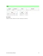
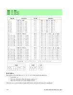
Page 113: ...ription The RDMODE instruction sets the C flag to the value of bit 0 of the System User Mode Register SU This instruction is implemented in the Rabbit 3000A RDMODE Opcode Instruction Clocks Operation...

Page 114: ...L bit 6 HL HL bit 7 DD CB d 86 DD CB d 8E DD CB d 96 DD CB d 9E DD CB d A6 DD CB d AE DD CB d B6 DD CB d BE RES b IX d RES bit 0 IX d RES bit 1 IX d RES bit 2 IX d RES bit 3 IX d RES bit 4 IX d RES bi...

Page 115: ...logical AND between the selected bit and its complement RES b r Opcode Instruction Clocks Operation b r A B C D E H L RES b r 4 2 2 r r bit CB 0 87 80 81 82 83 84 85 CB 1 8F 88 89 8A 8B 8C 8D CB 2 97...

Page 116: ...w order byte of PC with the data at the memory address in SP then loads the high order byte of PC with the data at the memory address immediately following the one held in SP The data in SP is then in...

Page 117: ...not set Z Z flag set NC C flag not set C C flag set LZ NV L V flag is not set LO V L V flag is set P S flag not set M S flag set RET f Opcode Instruction Operation C0 C8 D0 D8 E0 E8 F0 F8 RET f RET N...

Page 118: ...ata whose address is 1 higher than the data in SP and loads the high order byte of PC with the data whose address is two higher than the data in SP The data in SP is then incremented three times This...

Page 119: ...to the C flag See Figure 1 below Figure 1 The bit logic of the RL instruction Example If HL contains 0x4545 the byte in the memory location 0x4545 is 0110 1010 and the C flag is set then after the exe...

Page 120: ...in the register moves to the next high est order bit position bit 0 moves to bit 1 etc while the C flag moves to bit 0 and bit 15 moves to the C flag See figure below Figure 2 Bit logic of the RL ins...

Page 121: ...on bit 0 moves to bit 1 etc while the C flag moves to bit 0 and bit 7 moves to the C flag See Figure 1 on page 115 RL r Opcode Instruction Clocks Operation CB 17 CB 10 CB 11 CB 12 CB 13 CB 14 CB 15 RL...

Page 122: ...ontents of A Each bit in the register moves to the next highest order bit position bit 0 moves to bit 1 etc while the C flag moves to bit 0 and bit 7 moves to the C flag See Figure 1 on page 115 RLA O...

Page 123: ...3 The bit logic of the RLC instruction Example If HL contains 0x4545 the byte in the memory location 0x4545 is 0110 1010 and the C flag is set then after the execution of the operation RLC HL the byt...

Page 124: ...ves to both bit 0 and the C flag See Figure 3 on page 119 RLC r Opcode Instruction Clocks Operation CB 07 CB 00 CB 01 CB 02 CB 03 CB 04 CB 05 RLC r RLC A RLC B RLC C RLC D RLC E RLC H RLC L 4 2 2 4 2...

Page 125: ...A Each bit in the register moves to the next highest order bit position bit 0 moves to bit 1 etc while bit 7 moves to both bit 0 and the C flag See Figure 3 on page 119 RLCA Opcode Instruction Clocks...

Page 126: ...t d Bit 0 moves to the C flag bits 1 through 7 move to the next lowest order bit position and the C flag moves to bit 7 See figure below Figure 4 The bit logic for the RR instruction RR HL RR IX d RR...

Page 127: ...es to the C flag bits 1 through 15 move to the next lowest order bit position and the C flag moves to bit 15 see figure below Figure 5 The bit logic for the RR instruction RR DE RR HL Opcode Instructi...

Page 128: ...IX or IY Bit 0 moves to the C flag bits 1 through 15 move to the next lowest order bit position and the C flag moves to bit 15 See Figure 5 on page 123 RR IX RR IY Opcode Instruction Clocks Operation...

Page 129: ...move to the next lowest order bit position and the C flag moves to bit 7 See Figure 4 on page 122 RR r Opcode Instruction Clocks Operation CB 1F CB 18 CB 19 CB 1A CB 1B CB 1C CB 1D RR r RR A RR B RR C...

Page 130: ...t with the C flag the data in A Bit 0 moves to the C flag bits 1 through 7 move to the next lowest order bit position and the C flag moves to bit 7 See Figure 4 on page 122 RRA Opcode Instruction Cloc...

Page 131: ...lowest order bit position bit 7 moves to bit 6 etc while bit 0 moves to both bit 7 and the C flag See figure below Figure 6 The bit logic of the RRC instruction RRC HL RRC IX d RRC IY d Opcode Instru...

Page 132: ...oves to both bit 7 and the C flag See Figure 6 on page 127 RRC r Opcode Instruction Clocks Operation CB 0F CB 08 CB 09 CB 0A CB 0B CB 0C CB 0D RRC r RRC A RRC B RRC C RRC D RRC E RRC H RRC L 4 2 2 4 2...

Page 133: ...n A Each bit in the register moves to the next lowest order bit position bit 7 moves to bit 6 etc while bit 0 moves to both bit 7 and the C flag See Figure 6 on page 127 RRCA Opcode Instruction Clocks...

Page 134: ...ed by first loading the high order byte of the PC into the memory location with the address 1 less than the number in the Stack Pointer SP Then the low order byte of the PC is loaded into the memory l...

Page 135: ...rations output an inverted carry The C flag is set if A is less than the data being subtracted from it The C flag is cleared if A is greater than the data being subtracted from it The C flag is unchag...

Page 136: ...lag is set if A is less than the data being subtracted from it The C flag is cleared if A is greater than the data being subtracted from it The C flag is unchaged if A is equal to the data being subra...

Page 137: ...n the data being subtracted from it The C flag is cleared if A is greater than the data being subtracted from it The C flag is unchaged if A is equal to the data being subracted from it SBC HL ss Opco...

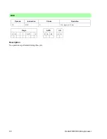
Page 138: ...134 Rabbit 2000 3000 Microprocessor Description Sets the C flag SCF Opcode Instruction Clocks Operation 37 SCF 2 CF 1 Flags ALTD I O S Z L V C F R SP S D 1...

Page 139: ...B d D6 DD CB d DE DD CB d E6 DD CB d EE DD CB d F6 DD CB d FE SET b IX d SET bit 0 IX d SET bit 1 IX d SET bit 2 IX d SET bit 3 IX d SET bit 4 IX d SET bit 5 IX d SET bit 6 IX d SET bit 7 IX d 13 13 1...

Page 140: ...D E H or L SET b r Opcode Instruction Clocks Operation SET b r 4 2 2 r r bit b r A B C D E H L CB 0 C7 C0 C1 C2 C3 C4 C5 CB 1 CF C8 C9 CA CB CC CD CB 2 D7 D0 D1 D2 D3 D4 D5 CB 3 DF D8 D9 DA DB DC DD C...

Page 141: ...the current processor mode and the previous 3 modes SETUSR shifts the contents of SU 2 bits to the left then sets bit 1 to 0 and bit 0 to 1 signifying user mode This instruction is privileged and only...

Page 142: ...shifted to the next highest order bit position bit 0 moves to bit 1 etc Bit 7 is shifted to the C flag Bit 0 is reset See figure below Figure 7 The bit logic of the SLA instruction SLA HL SLA IX d SL...

Page 143: ...1 etc Bit 7 is shifted to the C flag Bit 0 is reset See Figure 7 on page 138 SLA r Opcode Instruction Clocks Operation CB 27 CB 20 CB 21 CB 22 CB 23 CB 24 CB 25 SLA r SLA A SLA B SLA C SLA D SLA E SLA...

Page 144: ...xt lowest order bit position bit 7 is shifted to bit 6 etc Bit 7 is also cop ied to itself Bit 0 is shifted to the C flag See figure below Figure 8 The bit logic of the SRA instruction SRA HL SRA IX d...

Page 145: ...copied to itself Bit 0 is shifted to the C flag See Figure 8 on page 140 SRA r Opcode Instruction Clocks Operation CB 2F CB 28 CB 29 CB 2A CB 2B CB 2C CB 2D SRA r SRA A SRA B SRA C SRA D SRA E SRA H S...

Page 146: ...d to the next lowest order bit position Bit 7 shifts to bit 6 etc Bit 0 shift to the C flag Bit 7 is reset See figure below Figure 9 The bit logic of the SRL instruction SRL HL SRL IX d SRL IY d Opcod...

Page 147: ...0 shift to the C flag Bit 7 is reset See Figure 9 on page 142 SRL r Opcode Instruction Clocks Operation CB 3F CB 38 CB 39 CB 3A CB 3B CB 3C CB 3D SRL r SRL A SRL B SRL C SRL D SRL E SRL H SRL L 4 2 2...

Page 148: ...he sum of the data in IX and a displacement d or the sum of the data in IY and a displacement d The result is stored in A SUB HL SUB IX d SUB IY d Opcode Instruction Clocks Operation 96 SUB HL 5 2 1 2...

Page 149: ...Reference Manual 145 Description Subtracts from the data in A the 8 bit constant n The result is stored in A SUB n Opcode Instruction Clocks Operation D6 n SUB n 4 2 2 A A n Flags ALTD I O S Z L V C F...

Page 150: ...a in r any of the registers A B C D E H or L The result is stored in A SUB r Opcode Instruction Clocks Operation 97 90 91 92 93 94 95 SUB r SUB A SUB B SUB C SUB D SUB E SUB H SUB L 2 2 2 2 2 2 2 2 A...

Page 151: ...ents of the System User Mode Register SU 2 bits to the right replac ing the current processor mode with the previous mode This instruction is privileged and only implemented for the Rabbit 3000A SURES...

Page 152: ...he upper nibble of the 16 bit vector table address The vector table is always on a 100h boundary The push is accomplished by first loading the high order byte of the PC into the memory location with t...

Page 153: ...s value are stored memory at the address in HL and the upper 16 bits are stored in the alternate register DE If The data in IX IY and HL are then incremented and the data in BC is decremented The inst...

Page 154: ...ed etc The associated bit in the result byte is set if and only if one of the two compared bits is set The result is stored in A Example If HL contains 0x4000 and the memory location 0x4000 contains t...

Page 155: ...ng bits of each byte are compared i e bit 0 of both bytes are compared the bit 1 of both bytes are compared etc The associated bit in the result byte is set if and only if one of the two compared bits...

Page 156: ...s are compared bit 1 of both bytes are compared etc The associated bit in the result byte is set if and only if one of the two compared bits is set The result is stored in A XOR r Opcode Instruction C...

Page 157: ...C LD L D LD L E LD L H LD L L LD L HL LD L A 7 LD HL B LD HL C LD HL D LD HL E LD HL H LD HL L ALTD LD HL A LD A B LD A C LD A D LD A E LD A H LD A L LD A HL LD A A 8 ADD A B ADD A C ADD A D ADD A E...

Page 158: ...A 5 LD DE DE SBC HL DE LD mn DE EX SP HL IPSET 1 LD A I LD DE BC ADC HL DE LD DE mn IPRES IPSET 3 LD A R 6 LD HL DE SBC HL HL LD mn HL LDP HL HL LDP mn HL PUSH SU LD XPC A LD HL BC ADC HL HL LD HL mn...

Page 159: ...IX d LD C IX d 5 LD D IX d LD E IX d 6 LDP IX HL LDP mn IX LD H IX d LDP HL IX LDP IX mn LD L IX d 7 LD IX d B LD IX d C LD IX d D LD IX d E LD IX d H LD IX d L LD IX d A LD HL IX LD IX HL LD A IX d...

Page 160: ...IY d LD C IY d 5 LD D IY d LD E IY d 6 LDP IY HL LDP mn IY LD H IY d LDP HL IY LDP IY mn LD L IY d 7 LD IY d B LD IY d C LD IY d D LD IY d E LD IY d H LD IY d L LD IY d A LD HL IY LD IY HL LD A IY d...

Page 161: ...T 7 D BIT 7 E BIT 7 H BIT 7 L BIT 7 HL BIT 7 A 8 RES 0 B RES 0 C RES 0 D RES 0 E RES 0 H RES 0 L RES 0 HL RES 0 A RES 1 B RES 1 C RES 1 D RES 1 E RES 1 H RES 1 L RES 1 HL RES 1 A 9 RES 2 B RES 2 C RES...

Page 162: ...RL IX d RR IX d SLA IX d SRA IX d SRL IX d BIT 0 IX d BIT 1 IX d BIT 2 IX d BIT 3 IX d BIT 4 IX d BIT 5 IX d BIT 6 IX d BIT 7 IX d RES 0 IX d RES 1 IX d RES 2 IX d RES 3 IX d RES 4 IX d RES 5 IX d RES...

Page 163: ...RL IY d RR IY d SLA IY d SRA IY d SRL IY d BIT 0 IY d BIT 1 IY d BIT 2 IY d BIT 3 IY d BIT 4 IY d BIT 5 IY d BIT 6 IY d BIT 7 IY d RES 0 IY d RES 1 IY d RES 2 IY d RES 3 IY d RES 4 IY d RES 5 IY d RES...

Page 164: ...160 Instruction Reference Manual...

Page 165: ...instruction set by the Rabbit 2000 3000 An M indicates that this instruction is from the Z180 but has been modified A P indicates a privileged instruction Instruction Opcode byte 1 Opcode byte 2 Opco...

Page 166: ...1 2 3 f b V IY d IY d 1 DEC IX 11011101 00101011 4 2 2 IX IX 1 DEC IY 11111101 00101011 4 2 2 IY IY 1 DEC r 00 r 101 2 fr V r r 1 DEC ss 00ss1011 2 r ss ss 1 DJNZ e 00010000 e 2 5 2 2 1 r B B 1 if B 0...

Page 167: ...m 13 2 2 2 1 3 3 d mn L mn 1 H LD mn IX 11011101 00100010 n m 15 2 2 2 2 1 3 3 d mn IXL mn 1 IXH LD mn IY 11111101 00100010 n m 15 2 2 2 2 1 3 3 d mn IYL mn 1 IYH LD mn ss 11101101 01ss0011 n m 15 2...

Page 168: ...L HL 1 until BC 0 LDDSR 11101101 10011000 6 7i 2 2 1 2 3 2 i 1 d DE HL BC BC 1 HL HL 1 repeat while BC 0 LDI 11101101 10100000 10 2 2 1 2 3 d DE HL BC BC 1 DE DE 1 HL HL 1 LDIR 11101101 10110000 6 7i...

Page 169: ...101 11100001 9 2 2 1 2 2 IYL SP IYH SP 1 SP SP 2 POP SU 11101101 01101110 9 2 2 2 3 SU SP SP SP 1 P POP zz 11zz0001 7 2 1 2 2 r zzl SP zzh SP 1 SP SP 2 PUSH IP 11101101 01110110 9 2 2 2 3 SP 1 IP SP S...

Page 170: ...A IY d CY SBC IY d 10011110 5 2 1 2 fr s V A A HL CY SBC A n 11011110 n 4 2 2 fr V A A n CY SBC A r 10011 r 2 fr V A A r CY SBC HL ss 11101101 01ss0010 4 2 2 fr V HL HL ss CF SCF 00110111 2 f 1 CF 1...

Page 171: ...1000000 8 8i 2 2 2 2 2 3 1 i 2 CY DE HL IX IY DE DE CY BC BC 1 IX IX 1 IY IY 1 HL HL 1 repeat while BC 0 UMS 11101101 11001000 8 8i 2 2 2 2 2 3 1 i 2 CY DE HL IX IY DE DE CY BC BC 1 IX IX 1 IY IY 1 HL...

Page 172: ...168 Rabbit 2000 3000 Microprocessor...

Page 173: ...between the customer and Rabbit Semiconductor prior to use Life support devices or systems are devices or systems intended for surgical implantation into the body or to sustain life and whose failure...

Page 174: ...170 Rabbit 2000 3000 Microprocessor...

Reviews: